Week 8 - Challenge 2 - Switch Bezel Design
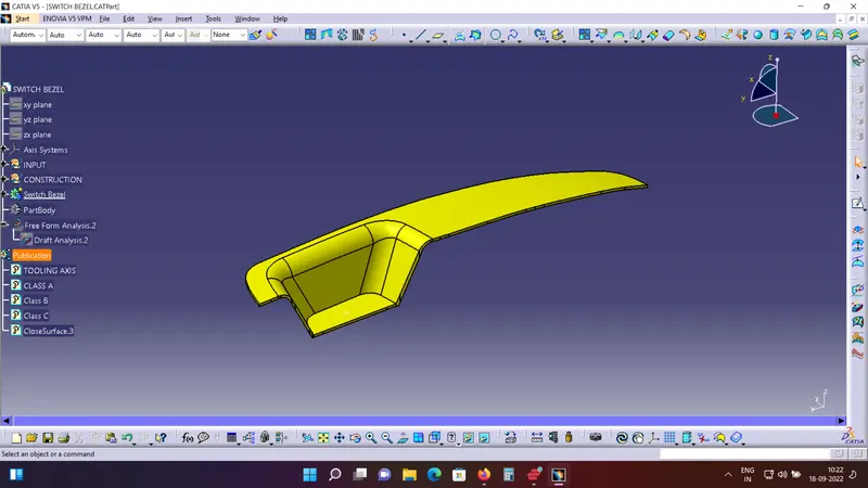
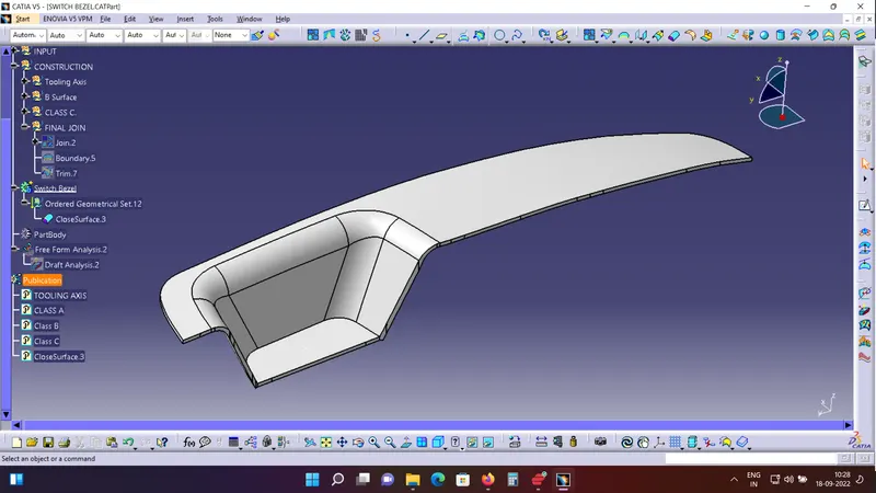
Below are the final Thickened class A surface and Solid Surface respectively.
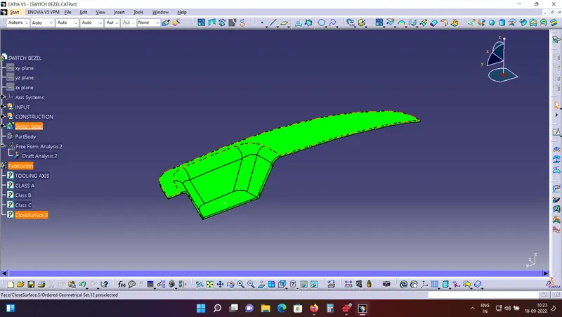
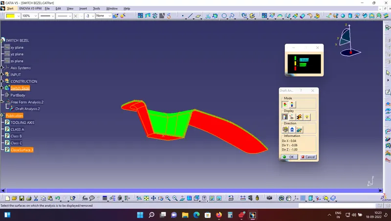
Below are the image for draft analysis:
Tools / Commands used:
- Extract
- Untrim
- Extrapolate
- Trim
- Join
- Draft Analysis
- Edge fillet
- Intersection
- Point
- Line: Point-Point and Bisecting methods
Procedure to create the tooling Axis:
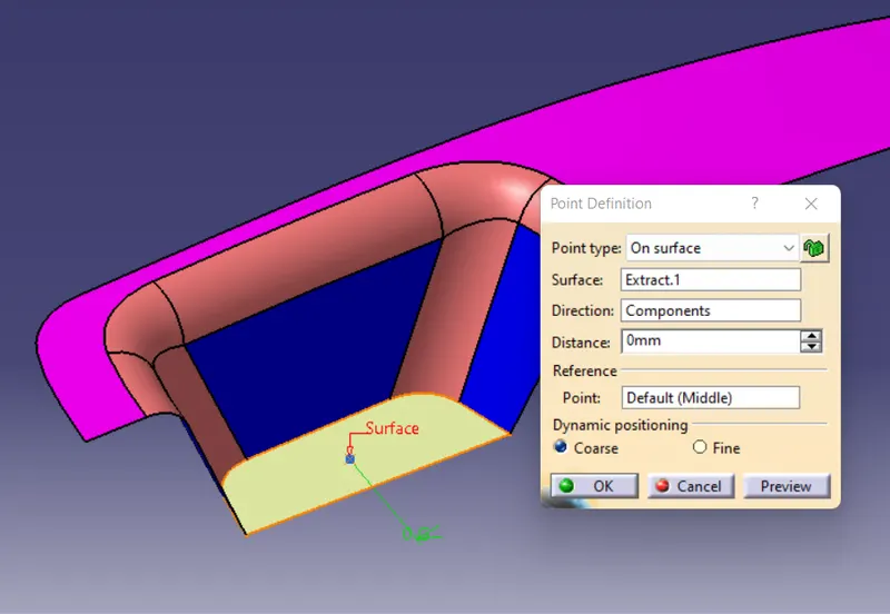
- Extract the base of the switch bezel and make a point ion the sirface. Input 0 as showed in the below image to get a point at the center of the surface. Insert and Axis system on the point
- Intersect the class A with the Y-Z Plane using the intersection command.

Draw Lines with Point-Point method projecting the two side faces on the intersecting line.
Draw a line Bisecting the two lines.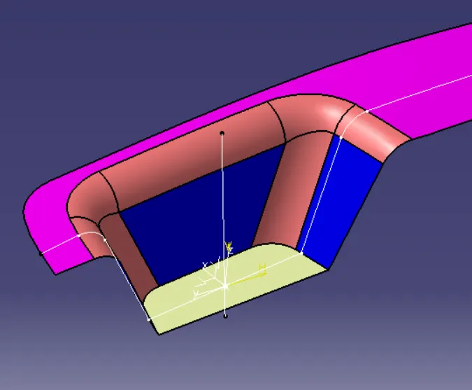
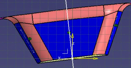
- Intersect the Class A with the X-Z plane using the intersection command.
Draw the line for the single side face available on the intersected line. (line 1)
Create a line from the origin using the Point Point method. (line 2)
Put the dimension of 6 degrees of line 2 with line 1.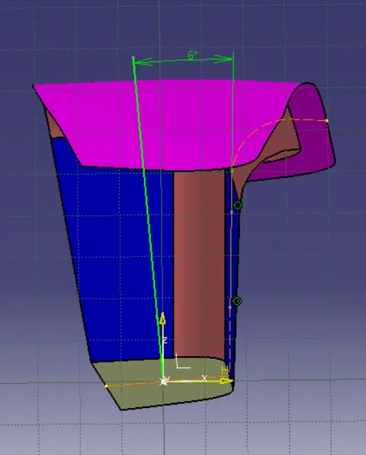
- Bisect the 2 lines created to get the final tooling Axis using the Bisecting Method.
- Publish the Tooling Axis.
Procedure to create the B surface:
- The original surface has fillets. Offseting the fillet surfaces will create errors and will not give the optimum results.
- Extract the side walls, Top surface, Bottom base surface.
- Untrim the extracted usrface.
- Extrapolate with surafces to intersect all the extracted surface.
- Trim off the excess surfaces.
Procedure to create the B surface:
- Use the multi extract command to extract the edges of the top Class A surface and Smoothen the surface using Curve smooth command.

- Use the sweep command to create the Class C surface.
- Extrapolate the edges tp intersect the two surfaces and Trim the excess parts.
- Finally join the Class A and Class B surface. Use Join parameters of Maximum 0.003mm
- If still we are not able to get the final join then extrapolate any surface by a small value and re trim both the surfaces to get the final join.
- Tip: To check if the final join has taken place properly, use the boundary command to visualize the boundaey and check if there are any open edges than which we require.
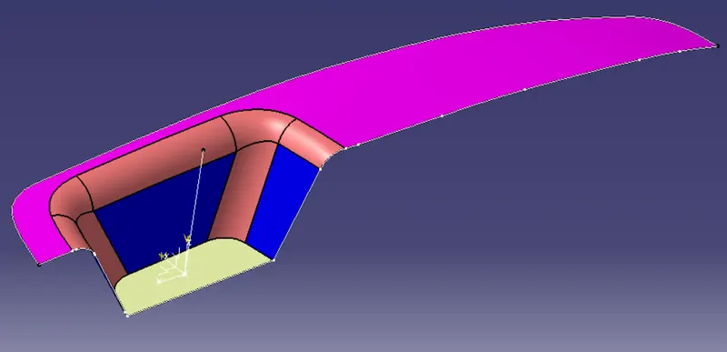
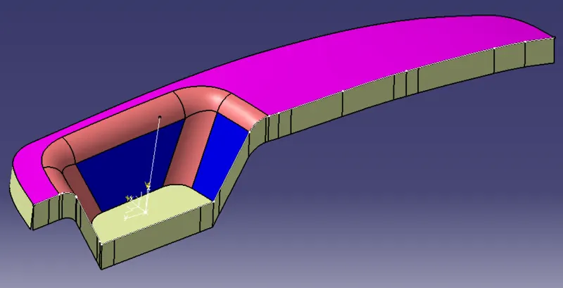
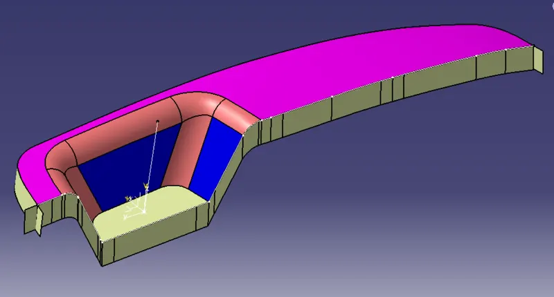
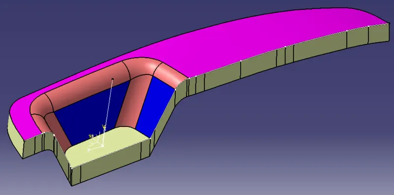
Procedure to do the draft analysis:
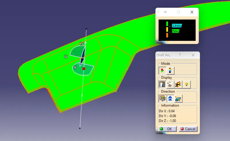
- Use command draft analsysis. Insert -> analysis -> Draft analysis.
- Locate the compass on the tooling axis.
- Set the desired degree of draft required in the color scale
- Visualize the result and make any required changes to the tooling axis if required.
- We can also analyze under running point to get the draft value at that specific point.