Week 8 - Challenge 2 - Switch Bezel Design
Aim:
To create a Switch Bezel solide model Catia V5 Generactive Surface workbench with the give class A surface.
Report:
Tooling Axis Creaction:
- First the given seperate Class A surface was Get united with Trimm Commend.
- Now acompete single surface workbench is Achived.
- now new geomentrical set were created for tooling axis
- the tooling axis is given in Z direction . to create it first a point is created in the surface.
- then a new Axis is created which is not current.
- now with the intresetion on the respective opposite face is taken and aproper line is drawn in yx axis.
- now a bisecting line is created for that intersection. now in ZX Axis another line intrect with the surface is taken ad ploted a line which makes angle of 3 degree.(minimum drafting angle)
- after then the two line drawn taken as input and line is constructed as Bisecting line.
- now these is our Tooling Axis.
Surface B creaction:
- To create a surface b the class A surface taken as input . In these the side walls and the bottom cup flat and the swithch bracket taken as input from class A surface with Extract commend.
- Now allthe surfaces are get untrimed and extrapolted to Continuity as curvacture and propagaction mode as Point continuity with the length of 10mm.
- these surface is seperactly ofseted to 2.5mm length to opposite of class A surface.
- now all these surface are get to trimmed and get output as singel surface.
- Now the corners get Fillet with edge fillect option.
Surface C Creaction:
- The suface A boundries are taken as input by boundrie-->line between two point--> select line-->Ok.
- like wise the other side of boundries is created to sweep.
- In sweep-->Profile typr-->Line-->Choose Guide Curve-->Draft direction as Tooling Axis-->Draft agle:3 deg-->Draft length as 10mm-->Ok.
- Like wise the other surface is done . Now we have two surface with more Patches so gice smooth curves to the Bondrie lines to Avoide Patches.
- now the edges of the surface is not intersecting withe each other. so the edges only get extrapolated for 10mm .
- These two surfaces get trimmed.
Final Surface Creaction:
- The Surface A ab surface C is get Jointed as single surface using Joint Opction.
- the Surface B is uset to trim the current jointed surface .
- ow the final thicken surfave is creacted.
Solid Object Creaction:
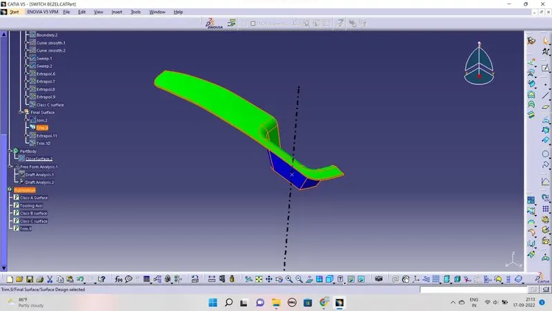
- Now open the part design workbench to create a solide object.
- click close body-->Click the final surface .
- Now the final solid model is creacted.
Surface Class A and Solide Draft analysis:
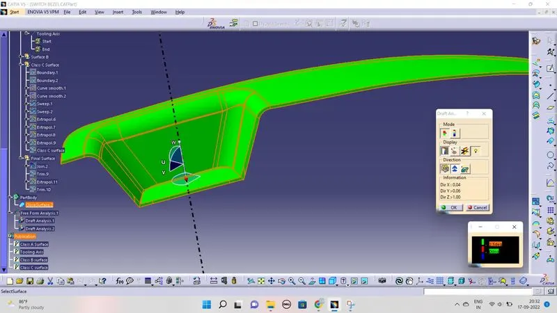
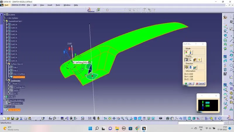
- Insert-->Analysis-->Fuecture Draft Analysis.
- click the Geomentric Body and get it to the tooling axisand lock with it.
- now click the insert Draft direction opction and click the surfac . If the choosen surface become Blue in Color then flip the draft Darection accordingly.
- Then click Analysis Under the Running Point Option and move cursor to surface and click it. it will give the draft direction an can be seen different draft angle to different surface point.
- if any value is seen to under the given Drafting angle we need to see any bundries is apperaing. if appeared the we neetd to edit the surface according to the drafting angle.
Therefore the Publication comend helps to access the sdurface quickly.
Drawing:
Draft Analysis of Class A Surface:
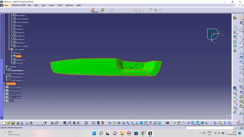
Solide Model:
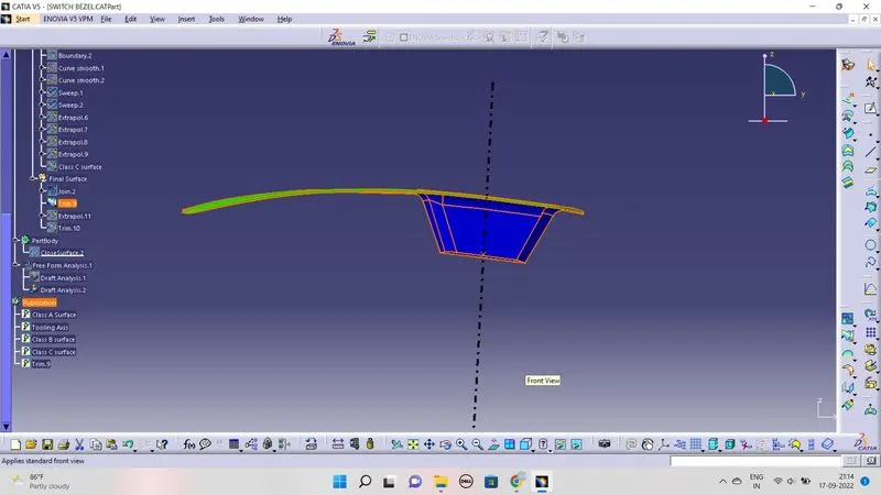
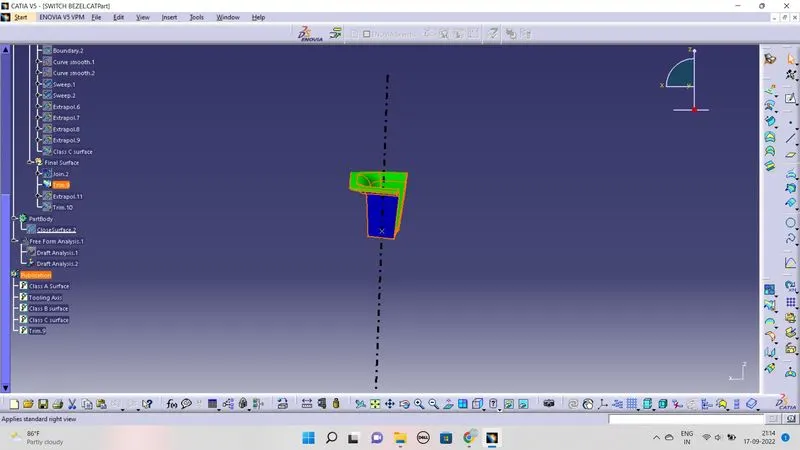
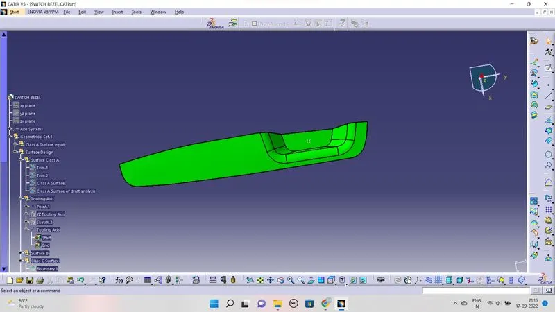
Tooling Axis View:
Result:
Thus te ive task has been complected.