Week 8 - Challenge 2 - Switch Bezel Design
OBJECTIVE:-
The objective of the project is to design the SWITCH BEZEL and to do a draft analysis for it by creating the required tooling direction with the help of the bisecting method.
what is SWITCH BEZEL
The control panel bezel is the frame part of the window switch that hold its switch cover and buttons into place. moulding is the method used to manufactured the plastic trim of an automotive by most OEM's, hence by considering the manufacturing consideration the switch bezel is desiigned.
DESIGN CONSIDERATION
- Class - A surface should be aesthetically smooth and good.
- Class - B surface should have all the supporting features like ribs.
- parting line should concide with B surface since flashing couldnt effect the aesthetic of class - A.
- Class - C surface should also pass the draft analysis.
PROCEDURE FOR CREATING THE SWITCH BEZEL AS SHOWN BELOW
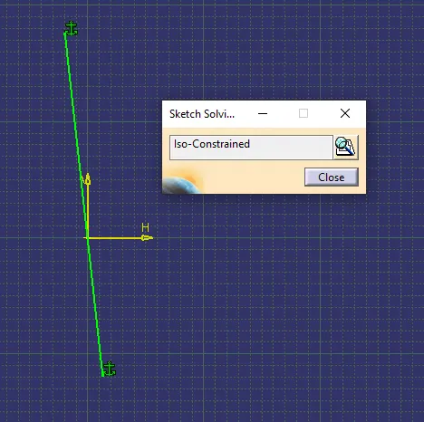
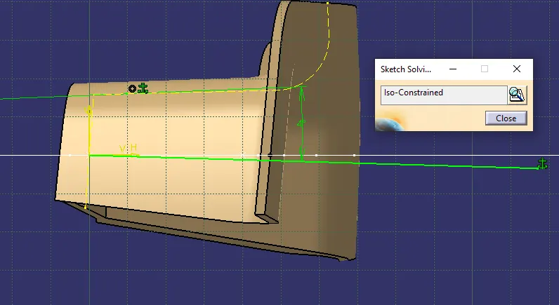
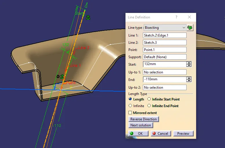
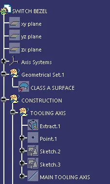
- We first created the tooling axis by first crerating the dummy axis from x and y diretion and along the z direction we bisect the line and created the main tooling axis
- Then with class A surface we started extract the surface to create the B surface creation
sketch 2
sketch 3
MAIN TOOLING AXIS from the sketch 3
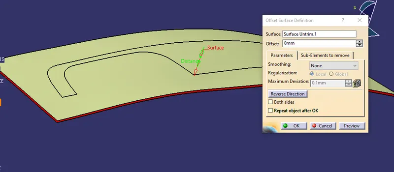
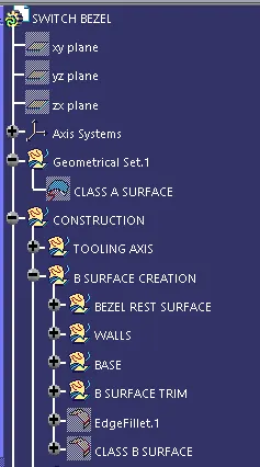
B SURFACE CREATION
selected the face of the bezel resting surface and untrim the surfce and extrapolate the surface and offset it by 2.5mm
Then we extrapolate the walls of the switch bezel and trim the walls to required surfce with rsespect to class A surface and then offset it by 2.5mm
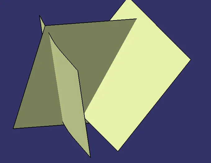
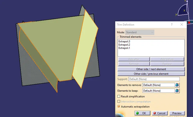
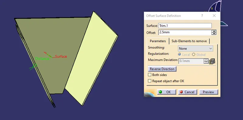
Then for the base we extract the surface from the class A surface and then untrrim the surface and extrapolate the surface and offest it by 2.5 mm
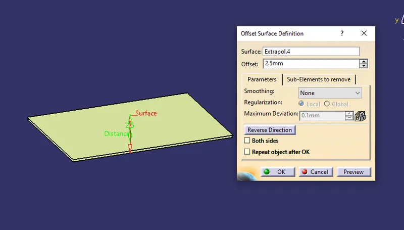
Then we do the final trimming of the base, walls and the resting surface of the switch bezel
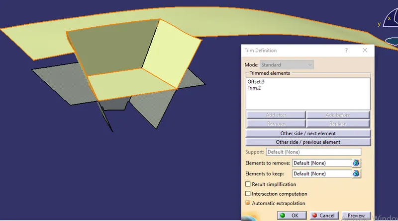
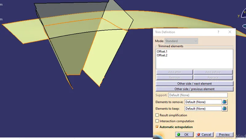
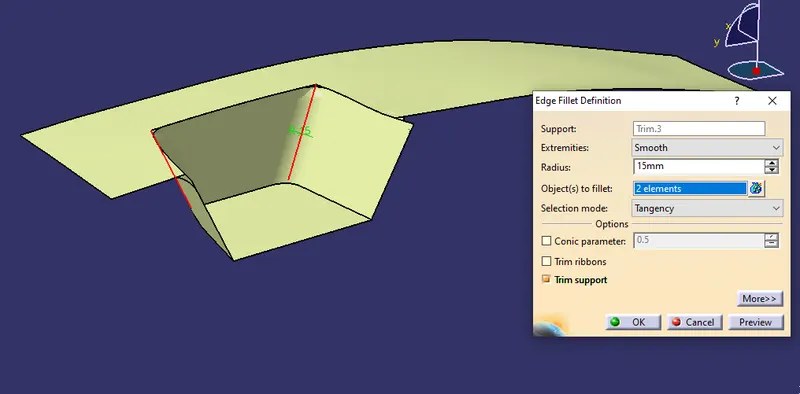
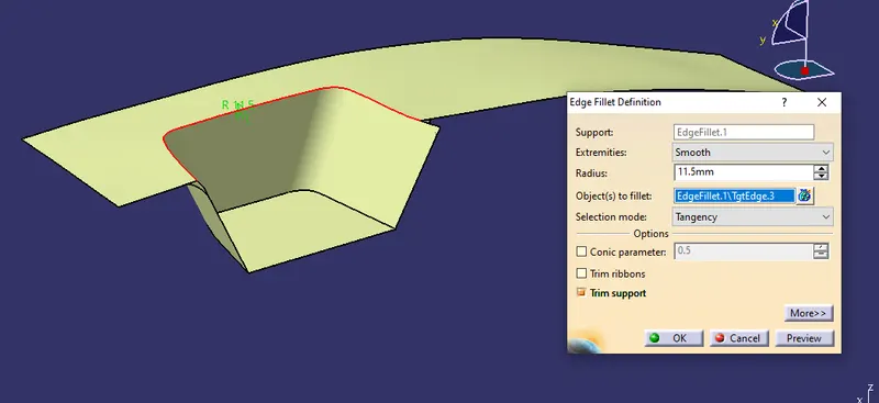
Then we provide the fillet to the final trim of the class B surface
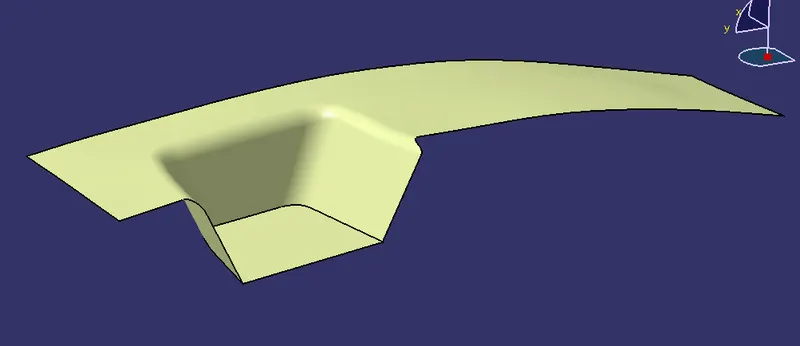
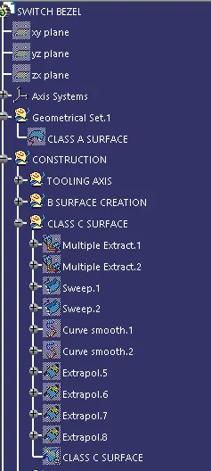
Then we create the multiple extract from the class A surface to create the Class C surface as shown below
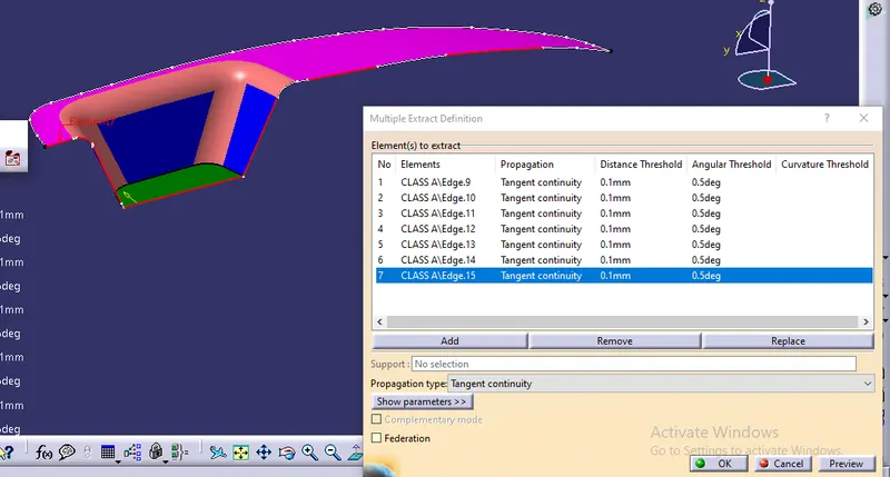
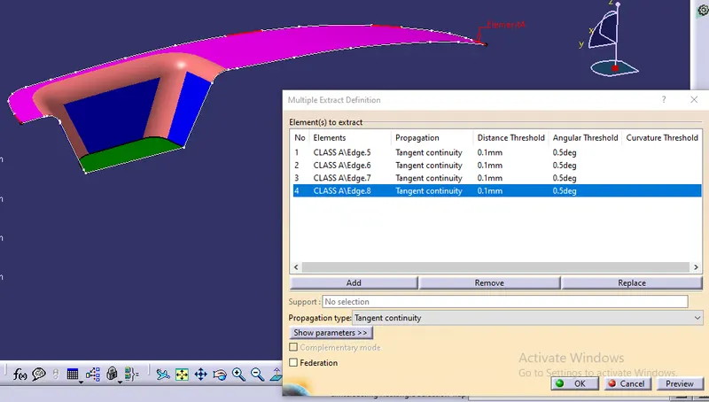
Then with help of sweep command with draft direction with respect to the tooling axis we created the class B surface as shown below
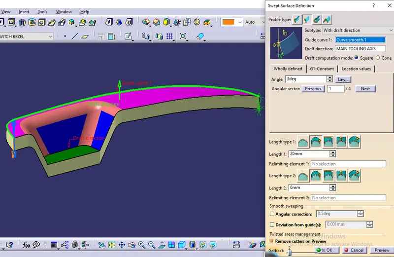
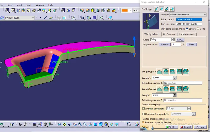
Then trim the boundry of the class c surface using the extrpolate command
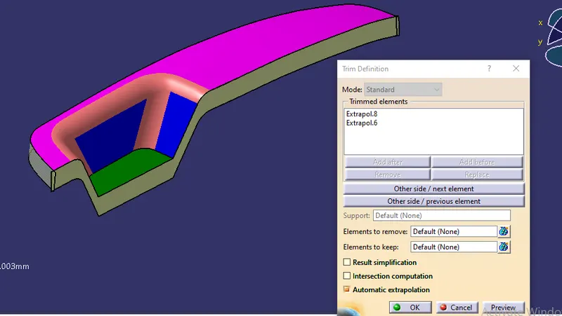
then join the class A with class C and trim with class B surface
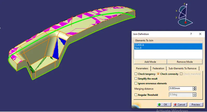
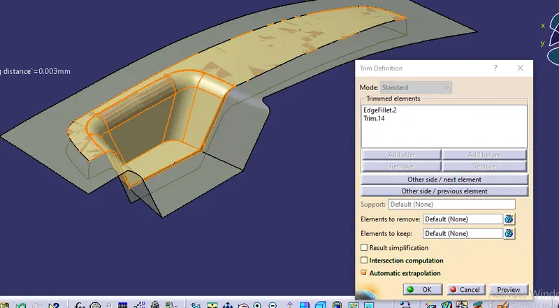
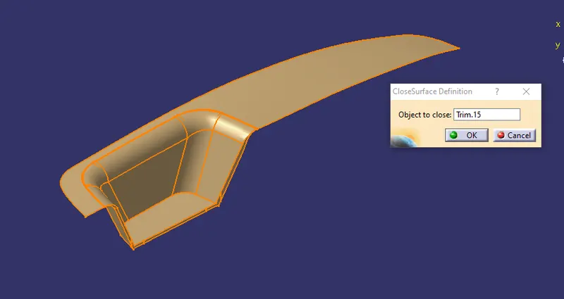
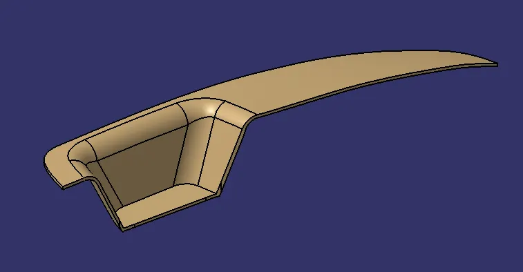
and created the close surface with the part body in the part design as shown below
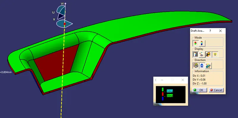
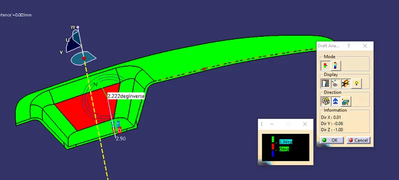
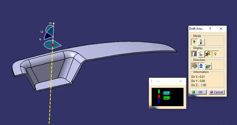
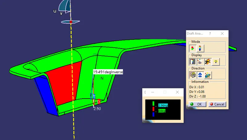
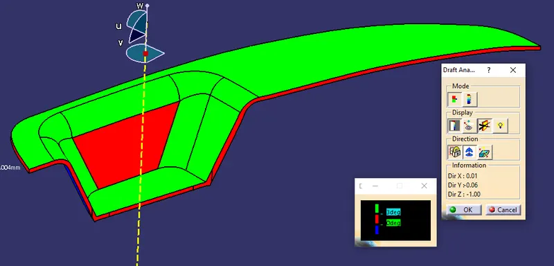
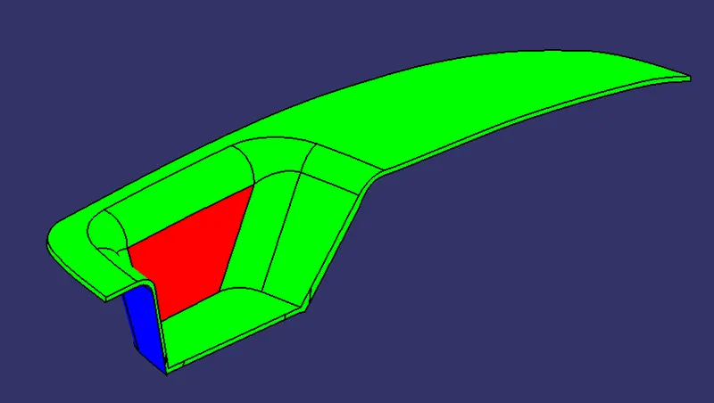
DRAFTING ANALYSIS done on the basis of the material selected and tooling axis
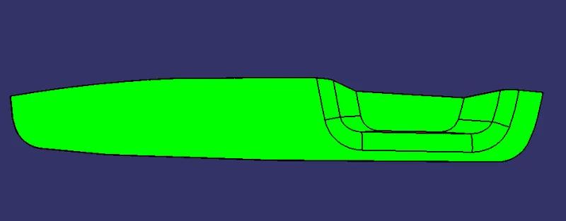
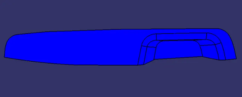
ORIENTATION VIEWS
ISOMETRIC VIEW
FRONT VIEW
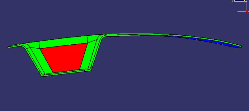
SIDE VIEW
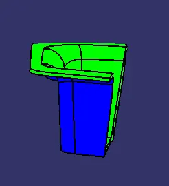
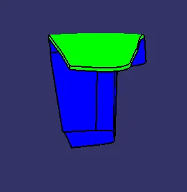
TOP VIEW
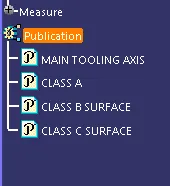
TREE STRUCTURE
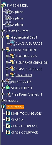
CLOSED SURFACE
CONCLUSION :-
Finally the class -A ,B & C surface with the Tooling Direction have been published and the switch bezel is moved on to the designing of the next operation - the creation of B - side feature.