Week 8 - Challenge 2 - Switch Bezel Design
SWITCH BEZEL CREATION
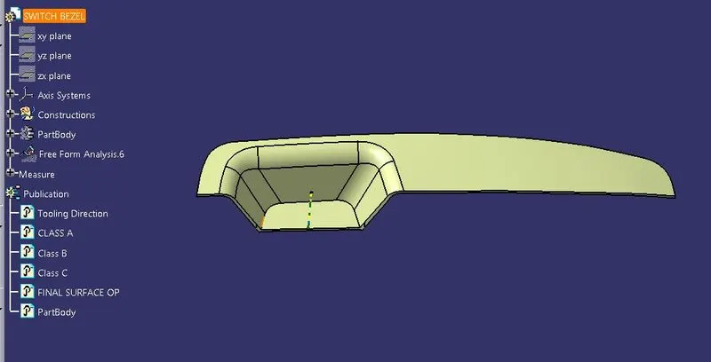
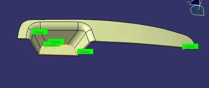
The switch bezels Part were done in stages which involved checking of th given class A surface for any open boundary, creation of best tooling axis, creation of Class B and Class C surfaces, combining the three surfaces and trimming them to get the desired shape and finally doing a generative draft analysis to ensure the model has a positive draft and can be produced. For convenience the part was modelled in different steps.
Step 1: Inspection of Class A surface and Creation of tooling axis
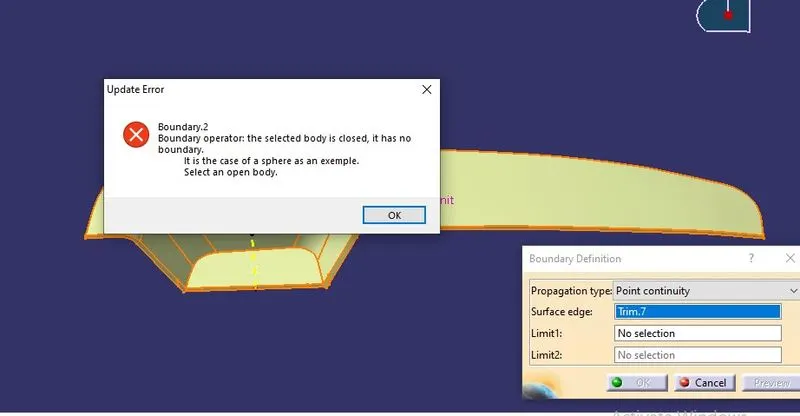
After inspection of the given class A surface for any open boundary, the selected base phase of switch bezel was selected and a point was created at the center of that component. An axis system is then created at that point.
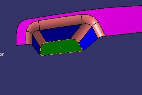
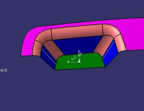
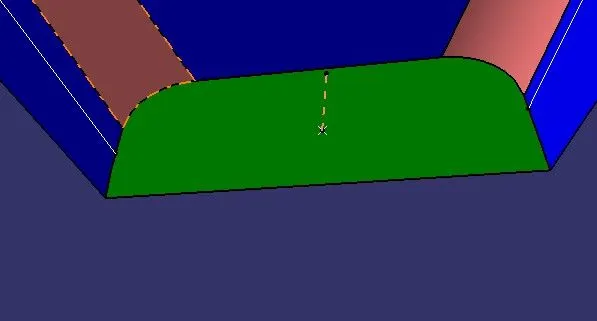
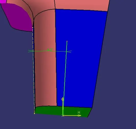
The final tooling direction is then bisected by using tooling direcion in x and y direction.
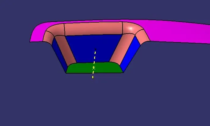
Step 2: Class B Creation
Class B surface was created by untrimming, extrapolating and offsetting every surface by the offset value except for the fillets. All the surfaces hence formed are then filleted with either the addition of offset value or with reduction of offset value depending on the position of fillet.
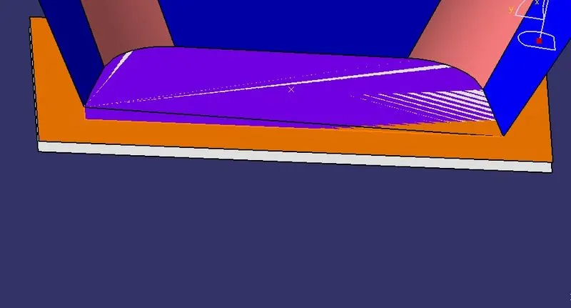
Class B surface procedure: untrim> [extrapolate all the outer edges> offset surface by the offset value]on all sufaces>trimming> filleting
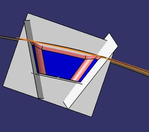
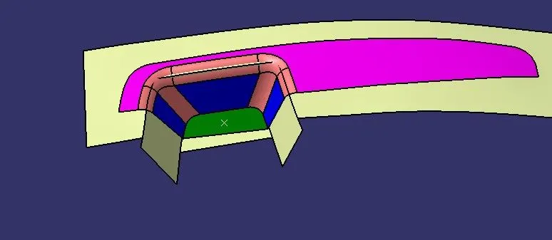
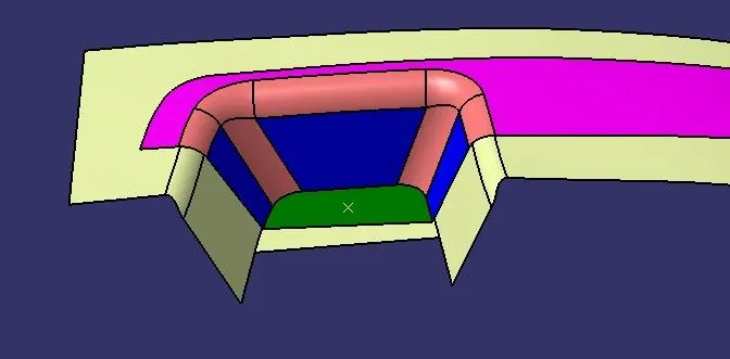
Step 3: Class C Surface Creation
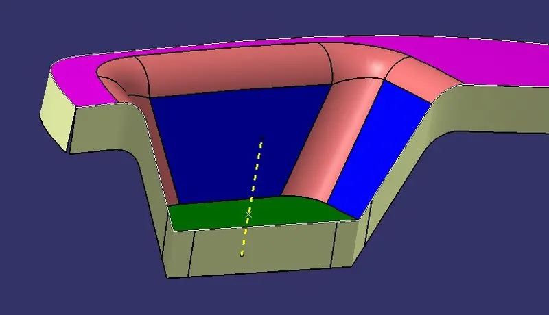
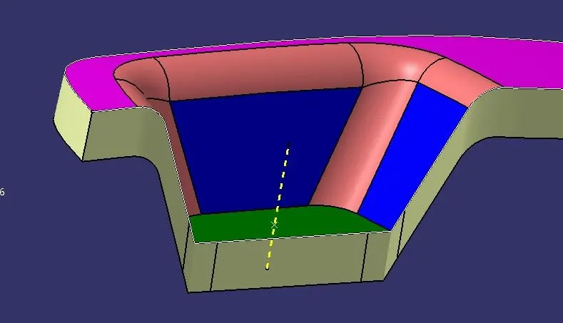
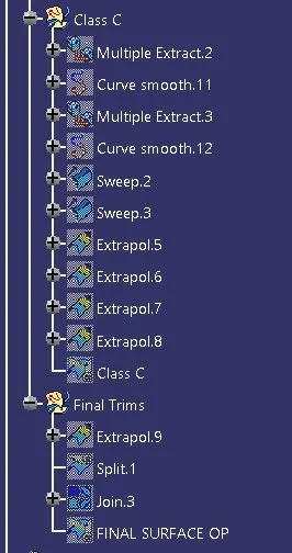
Class C surfaces are created by extruding the outer edges of class A surfaces with a positive draft along the tooling direction. The unjoint edges are later on extrapolated along its length and later trimmed to get a complete joint and hence forming a Class C surface
Step 4: Final joints and trims
After creation of Class A, B and C surfaces, Class A and Class C surfaces are joint. Make sure that there are no boundary forming at the joint between Class A and Class C, if this does not follow, we have to extrapolate the outer edges of either Class A or Class C until it follows later, the excess portion needs to be trimmed off. Finally, The joint surface needs to be trimeed with Class B surface to create the final output surface. Make sure that there are no boundary forming once the operation is complete. This surface is then later on converted to a solid body using Close Surface command.
Step 5: Draft Analysis
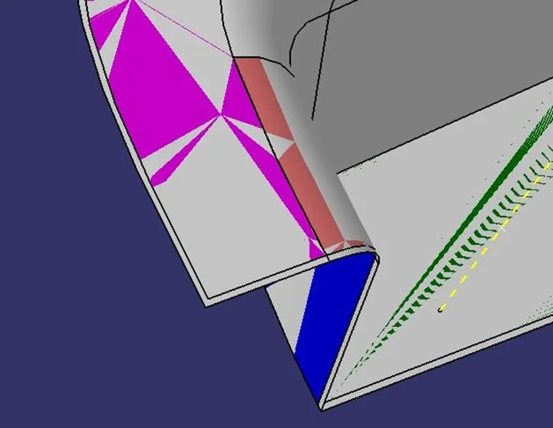
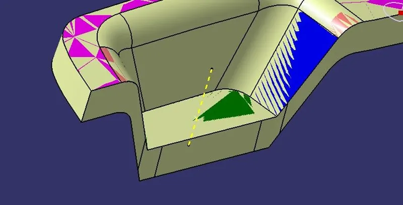
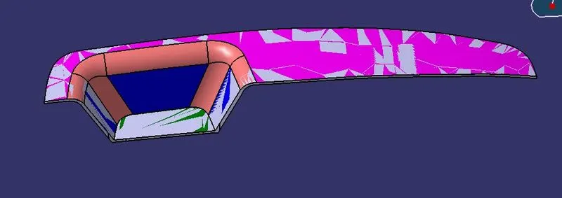
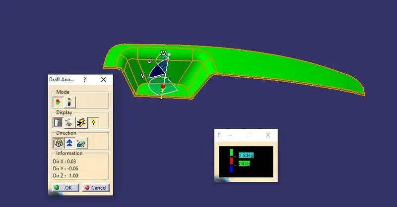
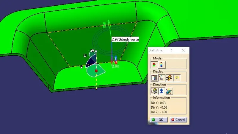
After the creation of solid body, the surface is finally checked if the final output is manufacturable by draft analysis. Inorder to do so, the body is kept in material mode and generative draft analysis is activated. If upon inspection, the draft is found less than 2.9 degrees, the tooling direction needs to be changed. In this case when the tooling direction in X-Z co-ordinate was at 3 degrees, the final draft was at 2.2 degrees and later on trial and error basis, we found the best results were produced if the tooling direction alon X-Z plane were at 4.5 degrees, the final draft analysis showed 2.93 degrees which meets our minimum requierment. (Generally, minimum is at 3, but in this case an exception was made as it did not make high difference)
Step 6: Final inspection
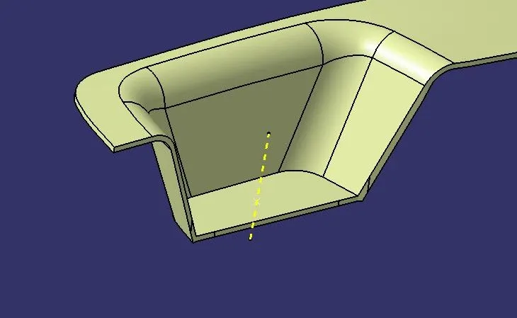
In this the final output is inspected to have equal thickness throughout and the surface does not have any open boundary.