Week 8 - Challenge 2 - Switch Bezel Design
AIM : To create the Switch Bezel Plastic component through the given Class-A surface.
Objective :-
To create a tooling direction.
To perform draft analysis of the plastic component.
To design the base bracket plastic component by creating the B-Surface and C-Surface using the given Class-A surface.
Class A Surface : Check the connectivity of the Class A Surface Ensure that there is no gap between the component, using join command. We can visually check it or by clicking boundary command. It has a boundaries outer. Therefore first check completed.
Below fig 1 shown the given class surface.
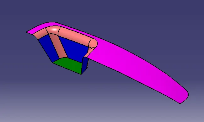
Fig 1.
Tooling Direction for Plastic Part : Tooling direction is main consideration for plastic part and mold parts because it defines movement of mold part and possibility of plastic part to come-out from mold part (Core and Cavity).
- In Molding machine arrangement is given to open the mold along a direction which is known as Tooling Direction.
- In other words. The mold is built from two separate halves (Core and Cavity) and tooling direction basically define the direction of mold pulls apart.
- Tooling direction is known as primary direction.
Preparation of Tooling Direction.
While creating the tooling direction in given class A surface. Chose the one suitable circle and draw the line direction of axis. as shown the below fig 1.1.
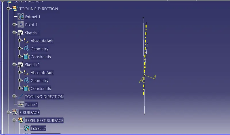
Fig 1.1.
Below fig 1.2 shown the A-Surface Draft analysis.
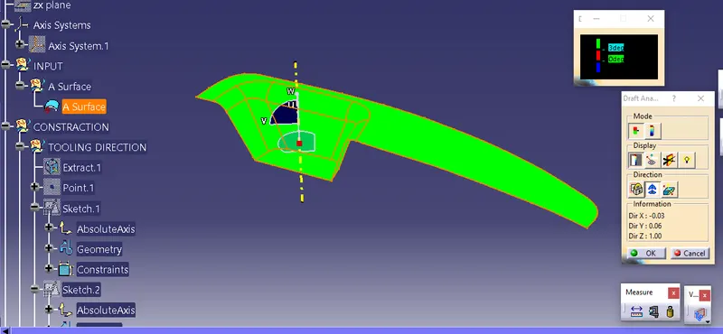
Fig 1.2.
Creation of B-Surface: Is created with help of A-Surface by using the Off-set and Trim command. Below fig 1.3 shown B-Surface.
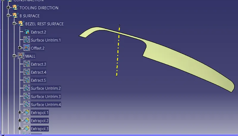
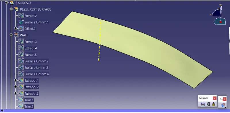
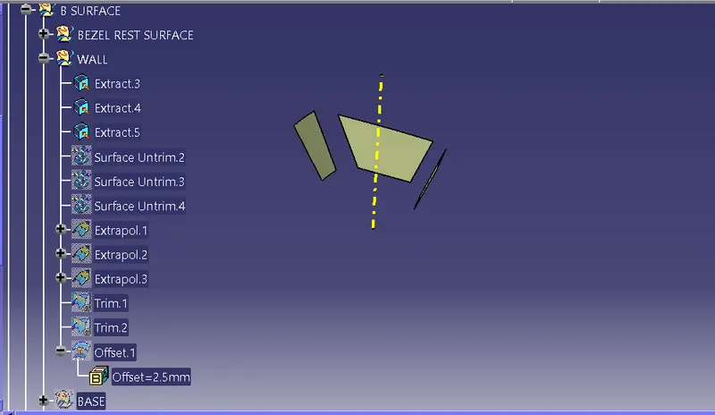
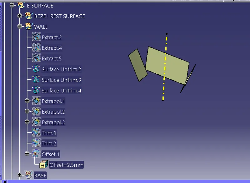
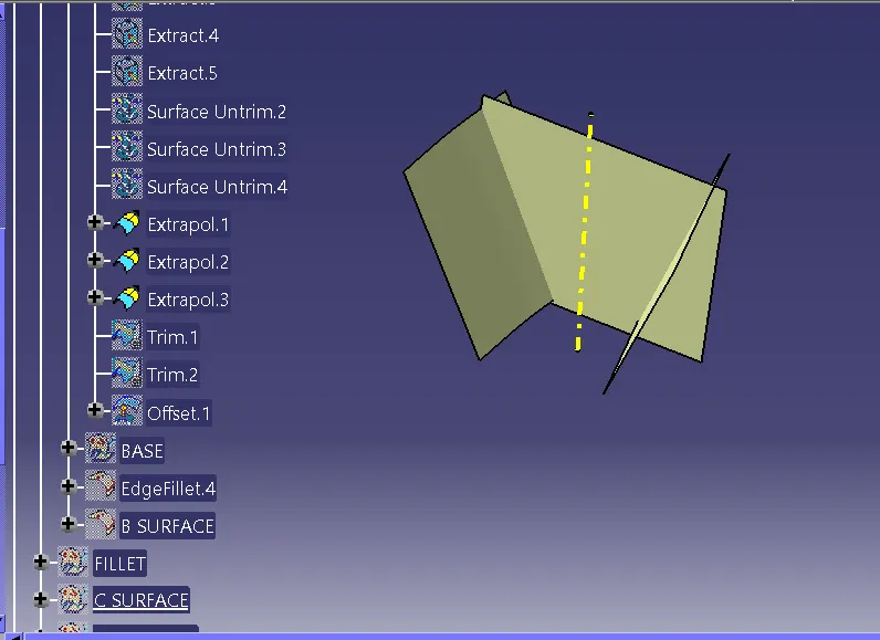
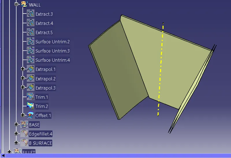
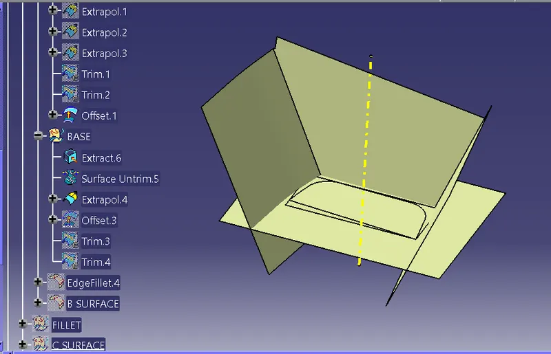
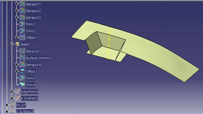
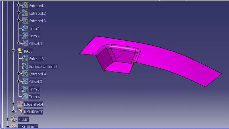
Fig 1.3
Creation of C-Surface: Is created with help of A-Surface by using the Sweep and Boundary command. Below fig 1.4 shown C-Surface.
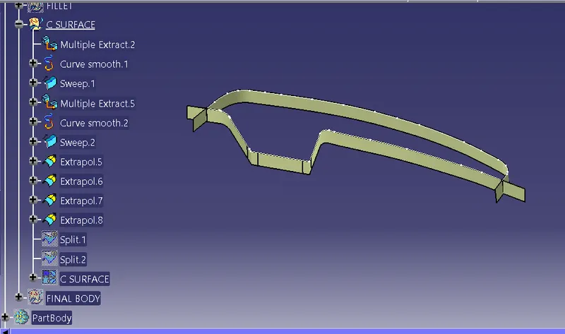
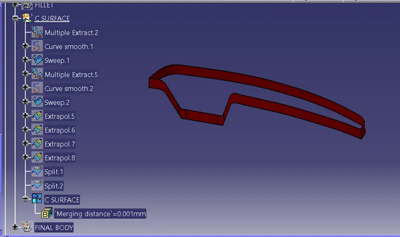
Fig 1.4
Below fig 1.5 shown the joing of A-surface and C-Surface with Draft analysis.
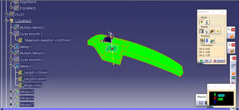
Fig 1.5
Below fig 1.6 shown Final Close Body with Draft analysis.
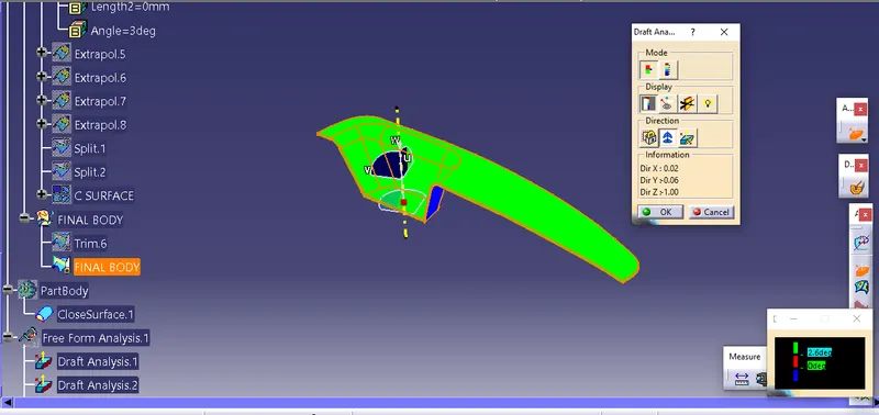
Fig 1.6
Below Fig 1.7 shown the Close Surface and some Publication.
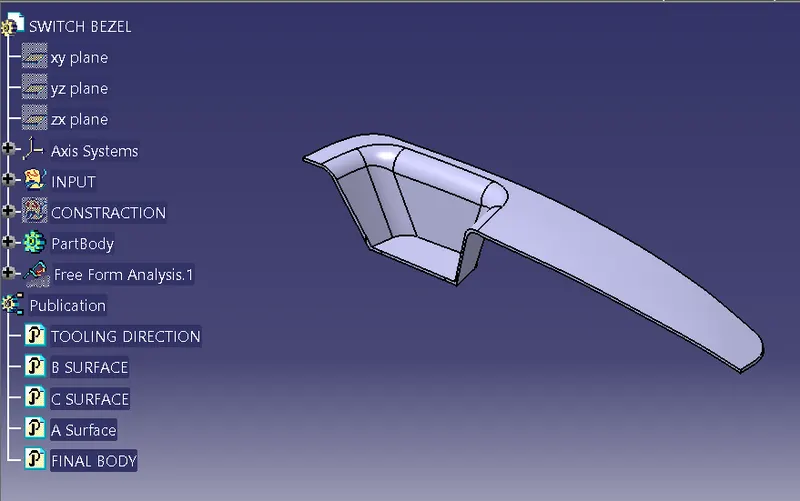
Fig 1.7
Below Fig 1.8 shown Dynamic Sectioning.
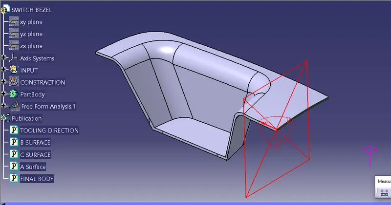
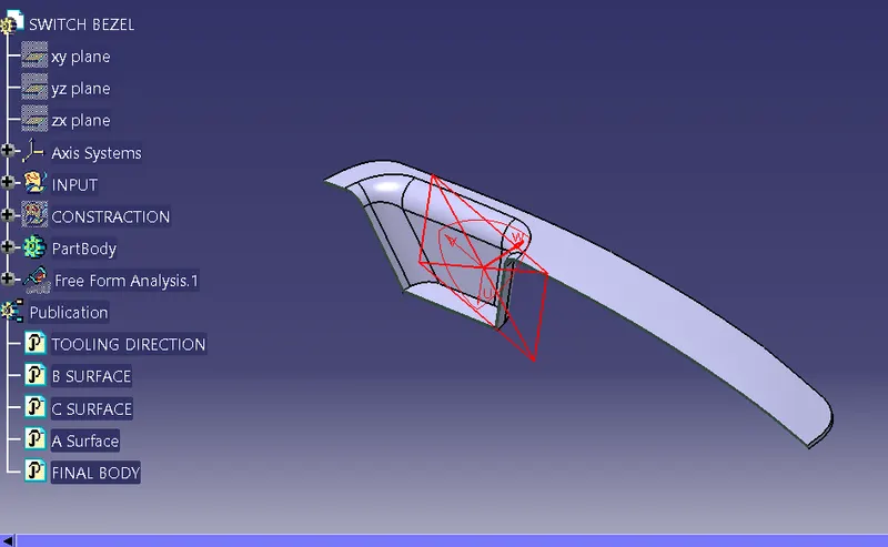
Fig 1.8
Below fig (1.9 to 1.12) shown solid model with the proper color code of the draft angle in various orientations (Isometric, Front, Side, and Top View)
Isometric View
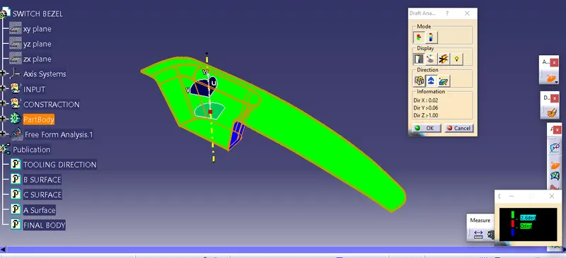
Fig 1.9
Front View
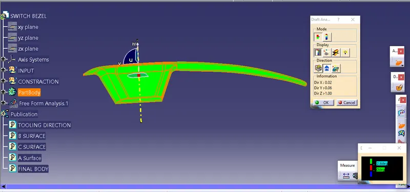
Fig 1.10
Side View
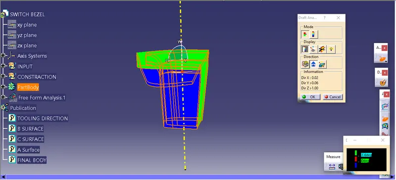
Fig 1.11
Top View
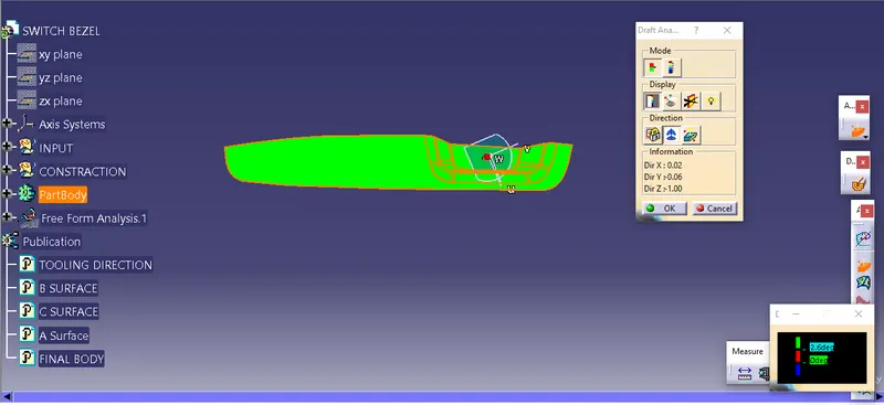
Fig 1.12
Conclusion : The SWITCH BEZEL is created with consedering all Design Methodology.