Week 8 - Challenge 2 - Switch Bezel Design
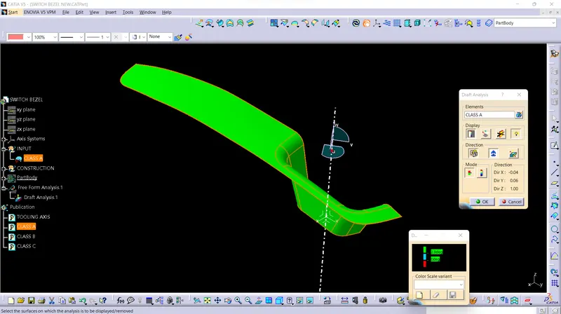
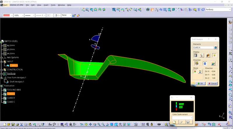
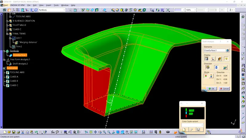
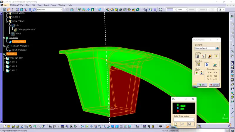
DRAFT ANALYSIS
Draft analysis is done inorder to check the part designed is manufacturable or not. if the designed component contain 90 degree wall or other obstruction aginst tooling axis it will create friction in mold wall and component while ejecting, designers try to avoid side cores inorder to reduce the cost of manufacturing.
so for the ease of removal of component from the mold, a small draft angle is recomented.
draf analysis will check the designed surface or solid body and represent draft angle provided in the form of colour changes. for draft analysis, tooling axis and dtaft angles are provided at the time of designing
bisecting method is one method used for idesntifying tooling axis
when a component is given, we assume direction of tooling by observing the component.
for example if we assume a component is tooling along z axis, we use bisecting method to find the dummy tooling axis along yz plane and xz plane. then we bisect these two lines to obtain our main tooling axis along z
for checking wheather the tooling axis created is right,we can simple try to view the component normal to tooling axis. all the surfaces should be visible while looking normal to tooling axis
bisecting method mainly involve creating intersection along planes to draw lines along drafted walls of the component. these lines are bisected to create dummy axises.