Week 8 - Challenge 2 - Switch Bezel Design
- DESIGN AND DRAFT ANALYSIS OF SWITCH BEZEL
1. OBJECTIVE:- The project's objective is to design the switch bezel and do a draft analysis for it by creating the required tooling direction with the help of bisecting method.
- To design switch bezel as per automotive original equipment manufacturer standard.
- Create B class and C class and tooling axis.
- Converting the close surfaces into the solid inside part workbench and providing the thickness of 2.5mm
- performing draft analysis to verify the creation of the tooling axis and c class section.
2. DESIGN CONSIDERATION:-
- CLASS-A:- A surface should be aesthetically smooth and good.
- CLASS-B:- B surface should have all the supporting features like ribs.
- The parting line should coincide with the B surface since flashing couldn't affect the aesthetic of class-A.
- CLASS-C:- C surface should also pass the draft analysis.
3. SOFTWARE:- CATIA V5 (Generative Shape Design)
4. ABSTRACT:- In this project, I design a switch bezel using Catia v5. I received input as class A Surface. I check the direction to eject the tool based on the component design. Later I checked whether all faces that intersected would clear the direction based on the tooling axis. I started working on the draft Analysis tool to check if our tooling direction clears the path for easy material removal from the tool. After that, I go class B creation using Advance tools from the surface followed by class c creation using the sweep command. After design A B C class surface, converting close surface into solid inside the part workbench.
5. INTRODUCTION:- The control panel bezel is the frame part of the window switch that holds its switch covers and buttons into place. Molding is the method used to manufacture the plastic trims of an automotive by most OEMs, hence by considering the manufacturing considerations the switch bezel is designed.
5. PROCEDURE FOR CREATING THE SWITCH BEZEL:-
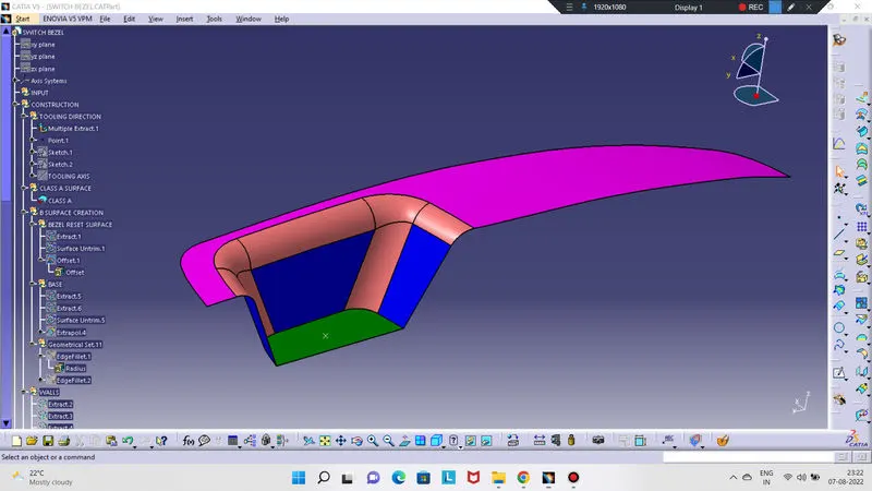
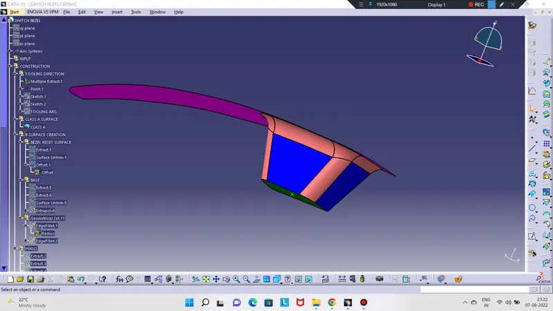
- First, the given styling surfaces are checked for any irregularities and if found they it is corrected by using trim, Extrapolate, Split and join commands.
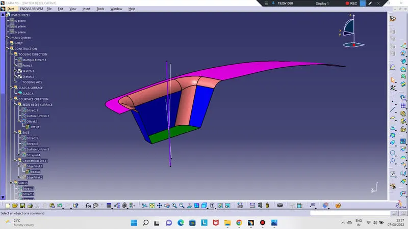
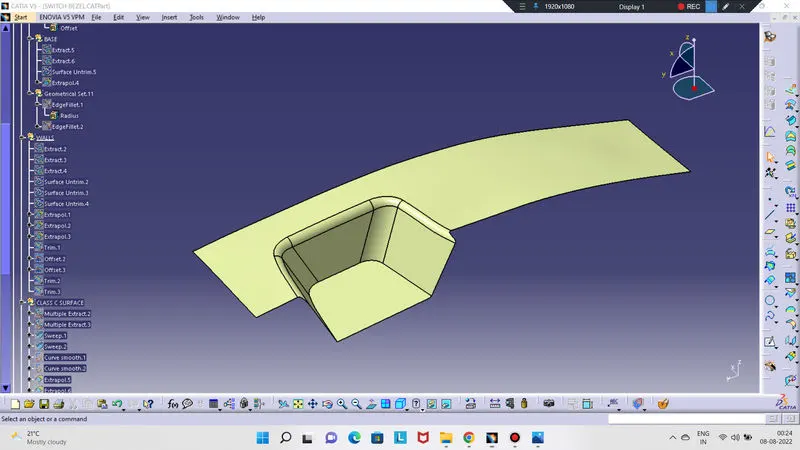
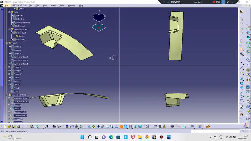
- The below image shows that the class-A surface is clean and no irregularities present, so let's move on to the next step.
6. CREATION OF TOOLING DIRECTION:-
- Considering the ejection from the cavity of the mold after manufacturing the interior trim (switch bezel) must have the nominal 3-degree draft angle.
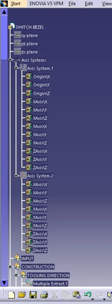
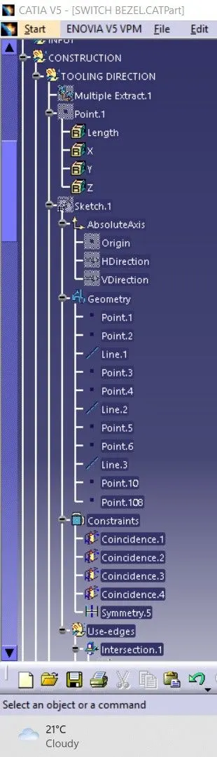
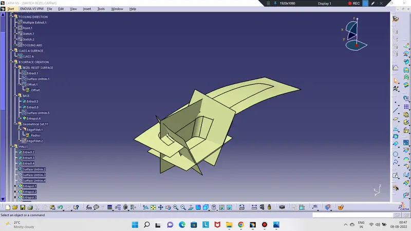
- Hence the tooling direction is created by considering and a point at the center is created and an axis system was inserted to the point with the current feature disabled.
- The base surface of class - A was extracted and a point at the center is created and an axis system was inserted to the point with the current feature disabled.
- Then, using project intersection along the y-z plane is created and the two inclined lines were drawn inside the positioned sketch.
- Then bisecting lines with the two inclined lines were drawn.
- Now the same procedure is done along the x-z plane but on one side we don't have inclined lines drawn inside the positioned sketch.
- Then bisecting lines with the two inclined lines were drawn.
- Now the same procedure is done along the x-z plane but on one side we don't have inclined lines so the center point is used to extrude a line along the z-direction and gave a measurement of 5 degrees (Tentatively).
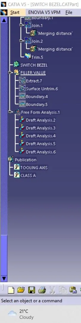
- With these two lines from sketches 1 and 2, the bisecting line is created and published as a tooling axis (Tooling direction).
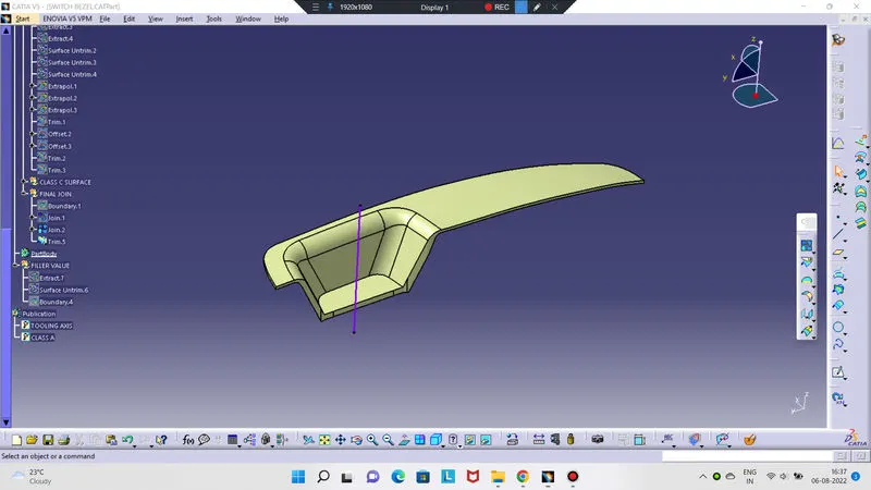
- When viewing from the tooling direction normal all the parts that are drafted should be visible so it gives a rough idea to determine product manufacturing in injection molding.
7. CREATION FOR B SURFACE CREATION:-
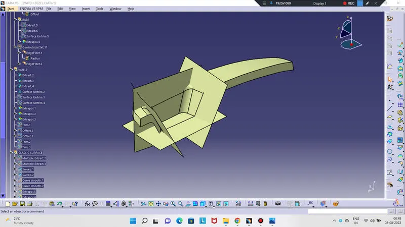
- The next step is to design B surfaces for the input which are usually the surfaces where all engineering aspects and support creations are done.
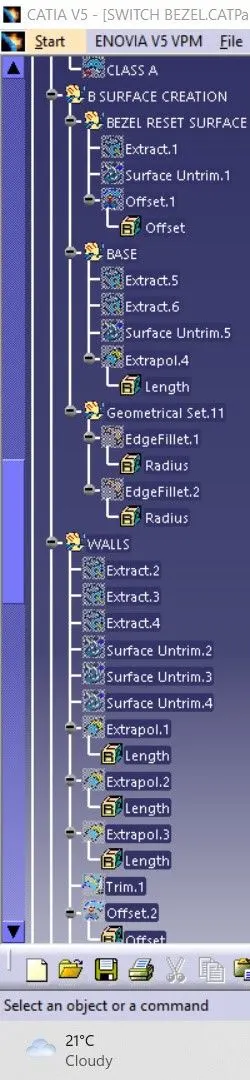
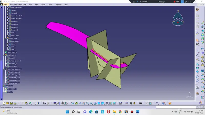
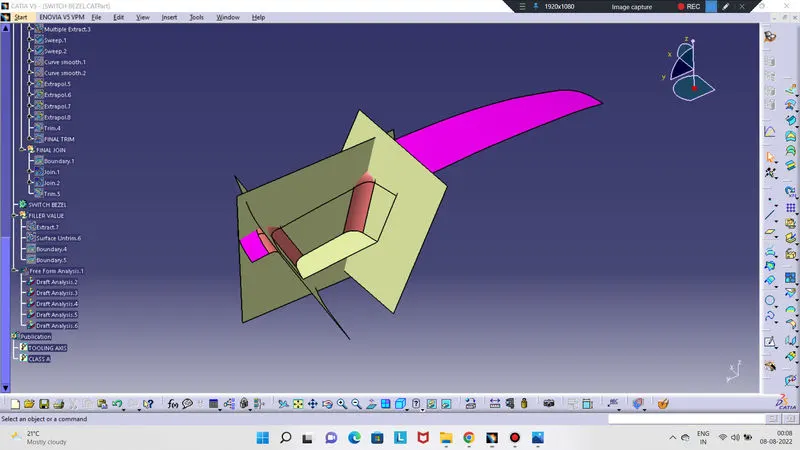
- The B surface Creation is performed using surface operations in CATIA which is an offset from class A with a dimension proportional to the thickness of the part
- In the switch bezel, the B surface is offset 2.5mm from the input which is the thickness of the part
- The B surface is an extrapolated surface compared to the A surface and forms the bottom skin of the part.
- Finally, the required corners have been filleted to 12.5mm (15mm-2.5mm). [15mm-fillet value of the A-surfaces, 2.5mm - Thickness of the component]
8. CREATION OF CLASS - C SURFACES:-
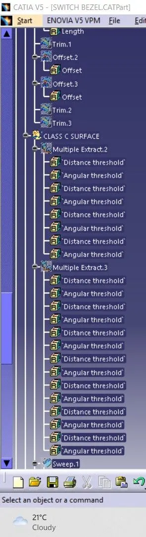
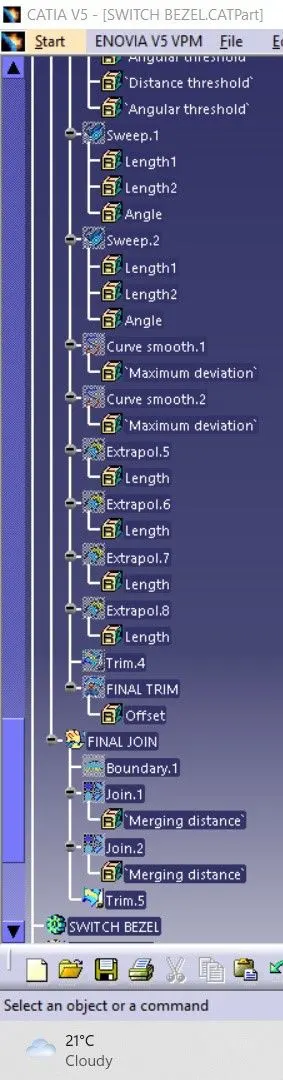
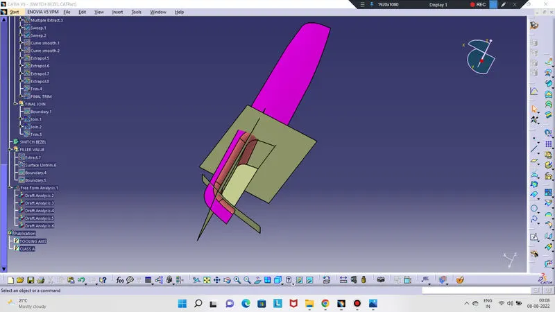
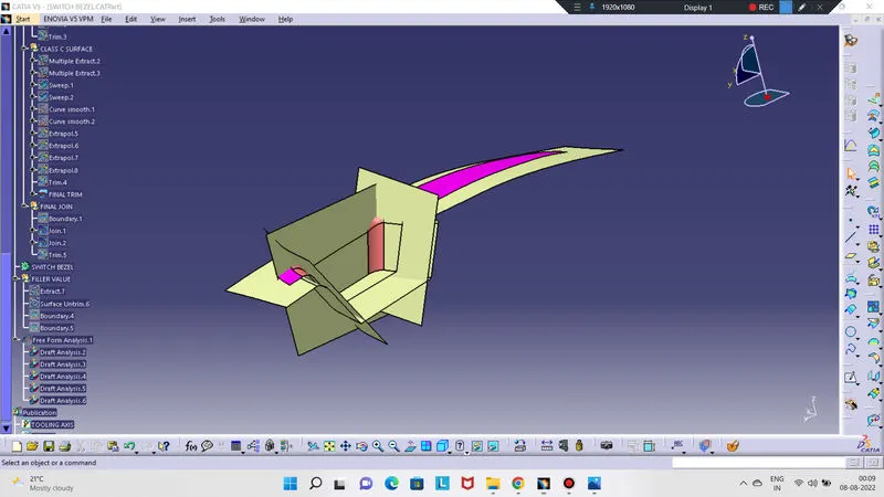
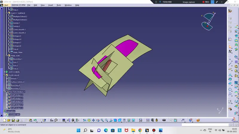
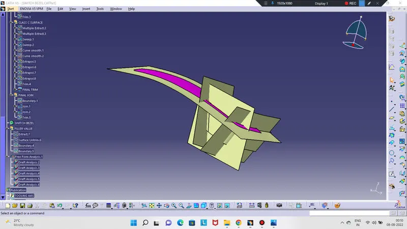
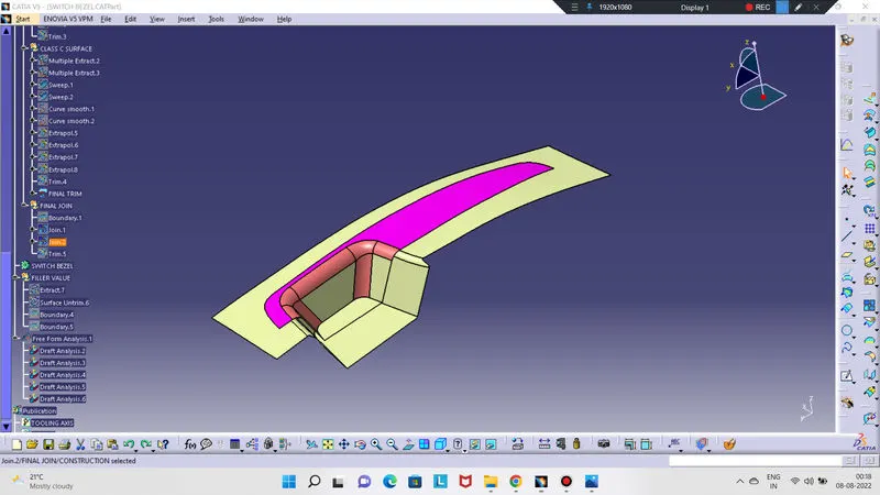
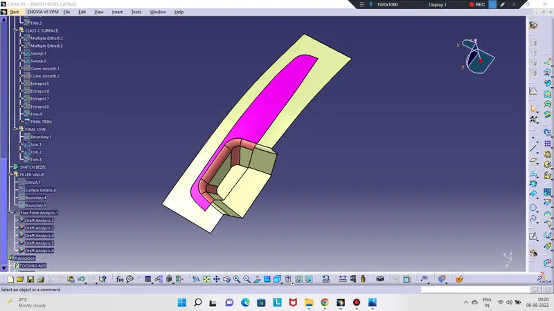
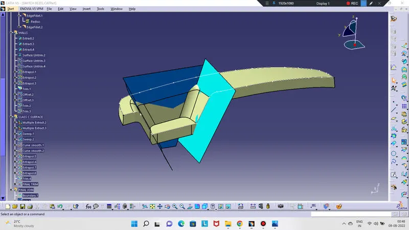
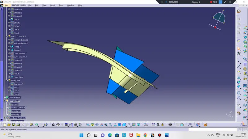
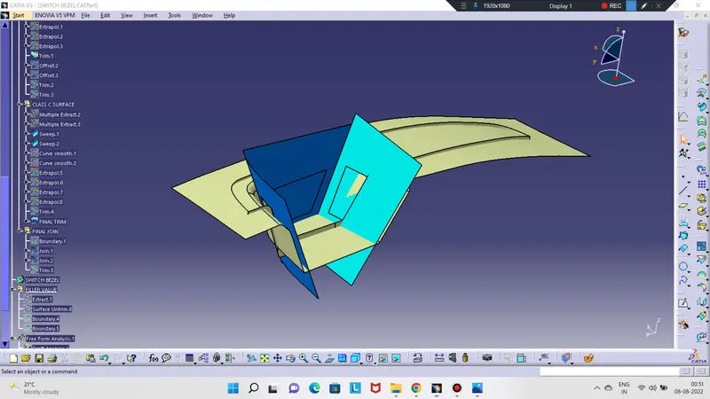
- The required outer edges of the A-surfaces were extracted using multiple extracts. Then for avoiding the patches the curve is smothered using the curve smooth option.
- Then by using the sweep command the surfaces were created with the following feature controls,
- Profile type - Line
- Subtype - With Draft Direction
- Guide Curve - Smooth Curve
- Draft Direction - Tooling Axis
- Draft Computation Mode - square
- Angle - 3 degree
- Angle Sector - Positive Downward (1)
- Length - 20mm
- Then By using extrapolate command the edges were intersected between the corners of the surfaces which eases the trimming operations.
- The direction of the sweep is the tooling direction formed earlier
- The draft angle for the sweep operation is provided which is 3 degrees and the surfaces are swept for length above the thickness of the specified part
- The c surfaces are refined using smooth curve options to remove the complexity and patches along the swept surfaces.
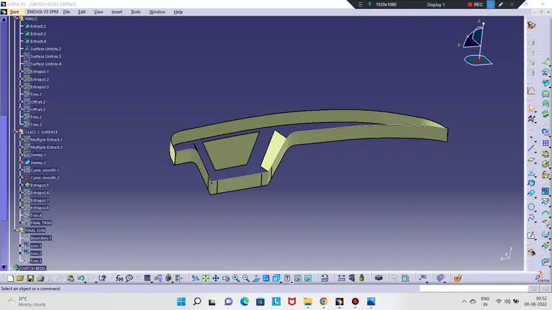
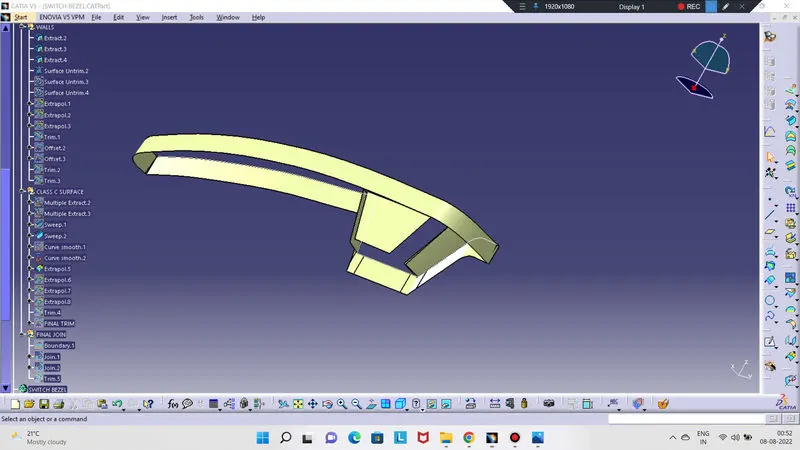
- Finally, the class A and class C surfaces are joined together and the connexity of surfaces should be less than 0.03mm, and the surfaces are merged.
9. CREATION OF CLOSED SURFACES:-
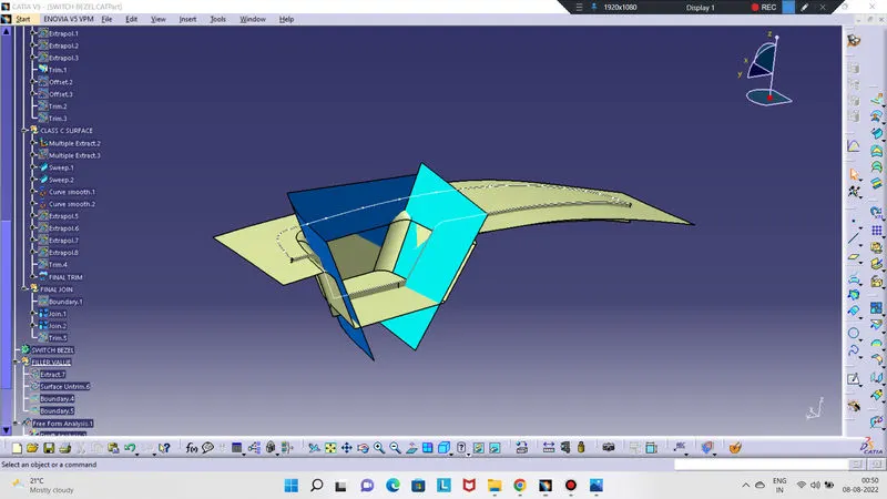
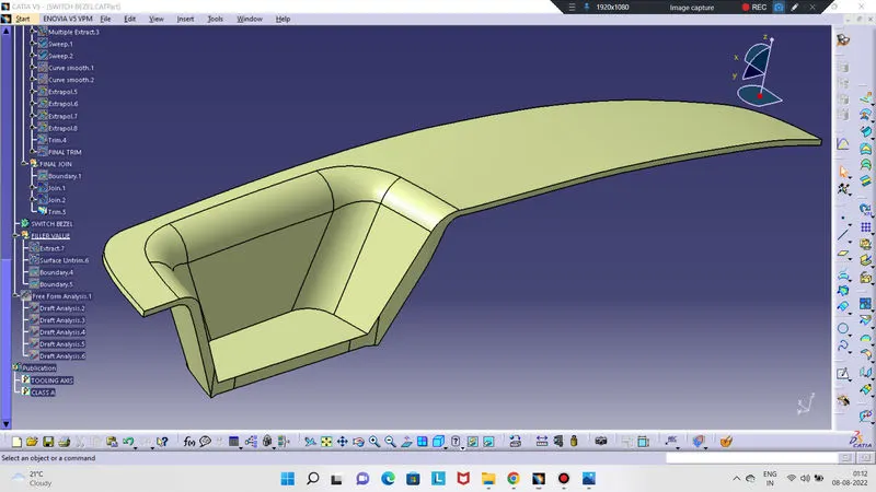
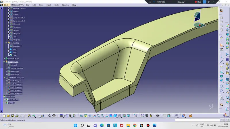
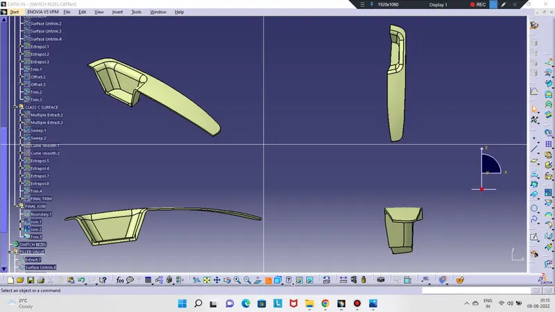
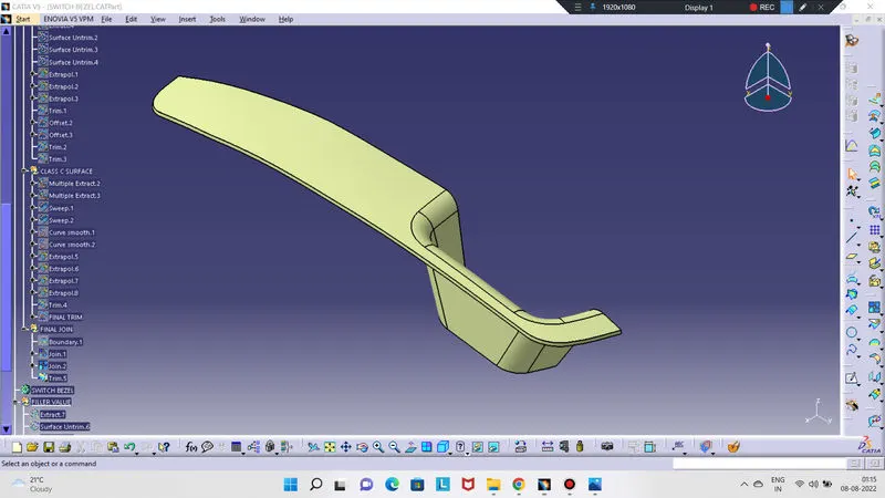
- Now the class-A and class-c surfaces were joined together by removing the gaps in-between them with the help of extrapolation(tangent continuity) and trim surface.
- The extract surfaces of the switch bezel were trimmed from the above-resulted trim surfaces with the class-B surfaces.
- Then, by defining the part body by using the closed surfaces command in part Design, the component's solid body is created.
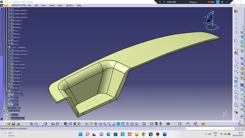
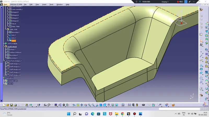
10. PROCEDURE FOR DRAFT ANALYSIS PROCEDURE:-
- The part created has to be changed to the material mode in a display frame.
- Then by enabling compass definition the axis system is pan along the direction of the part and aligned in line with the tooling direction.
- Lock direction is applied that fixes the compass and then the mode dialog box is formed by snapping at any point on the part
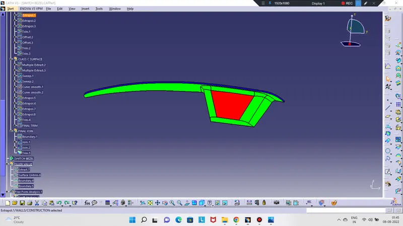
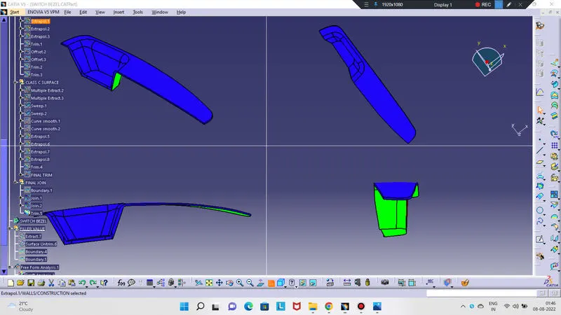
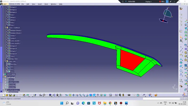
- The color codes are classified and draft Angle is applied.
- Then the running point analysis is used to hover around the part to analyze the permissible draft angles and the analysis is saved.
- Then the compass was activated and placed with the tooling axis by dragging the red pointer and then locked it.
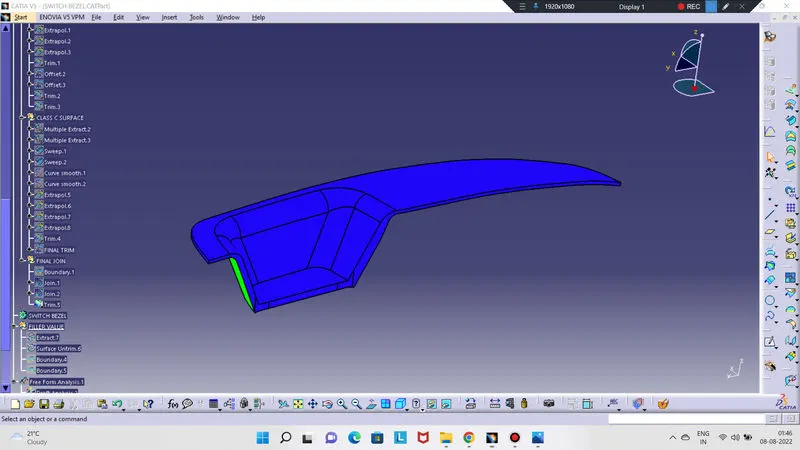
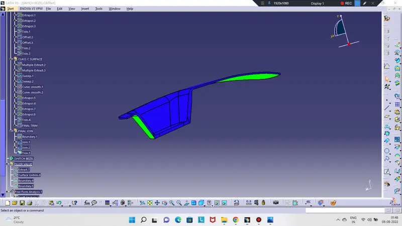
- Then, by selecting the quick analysis mode, the nominal value will be 3 degrees and checked for the component's draft angle.
- The green color area shows that if it satisfies the 3-degree draft angle. if not satisfied then by using the running point tool the area is measured and then altered to get a successful draft for the created tooling direction.
11. CONCLUSION:- Finally the class - A, B&C surfaces with the Tooling Direction have been published and the switch bezel is moved on to the design of the next operation-the creation of B-side features.