Week 8 - Challenge 1 - Base Bracket Design
AIM:- To create a base bracket plastic component through a given class A surface and perform a draft analysis of the final plastic component.
OBJECTIVES:-
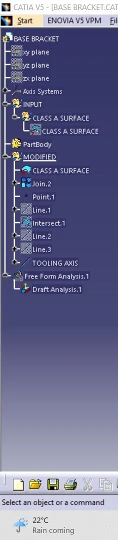
- Creation of tooling axis
- Creation of class b and class c surfaces
- Creation of a solid part out of surface modeling.
- Draft analysis of class surfaces and final plastic component.
INTRODUCTION:-
- CLASS-A SURFACE:- A surface made by the designer which is given as input to the plastic modeler to work on. It is an aesthetic surface and the outermost surface.
- CLASS-B SURFACES:- A surface below a certain thickness from the class-A surfaces is a class-b surface. This is the surface that contains engineering aspects of a model.
- CLASS-C SURFACES:- A surface that joins class-A and class-B surfaces is a class-C surface.
SOFTWARE:- CATIA V5 (GENERATIVE SHAPE DESIGN)
METHODOLOGY:- In this model, we have focused on the following things:
Tooling axis.
Drafting analysis
Class-B surface
Class-C surface
Making a solid model from the surface
The following tools were used to reach the final steps:-
1. Extract
2. Un-Trim
3. Trim
4. Extrapolate
5. Offset
6. Edge fillet
7. Boundary
8. Sweep
9. Join
10. Close (part design)
TOOLING AXIS:-
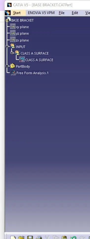
- First, ensure the class-a surfaces are properly joined and have no discontinuity on them. For this, we can use the boundary command or join command.
- Analyze the model manually or visually to see which direction is most suitable for the tooling axis.
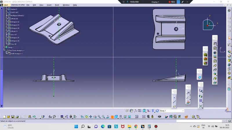
- As in the 3D view, we can see 2 holes and flat surfaces, we can directly take the tooling axis perpendicular to that. But to be sure, let us analyze from all the views. The below images of the front side and top views shows the areas that we have to keep in mind while choosing the tooling axis. As from X, we cannot see one hole so we cannot take the axis along this. In y we cannot see any holes so here too we cannot take the tooling axis. But in Z we can see 2 holes and flat surfaces so we can take the tooling axis.
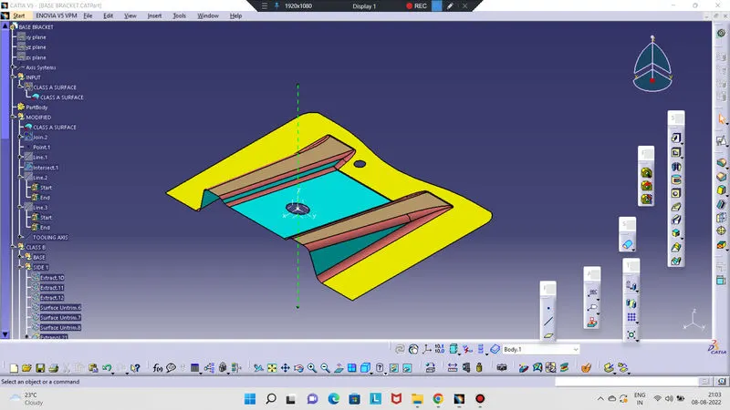
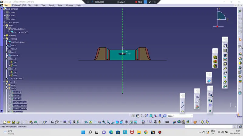
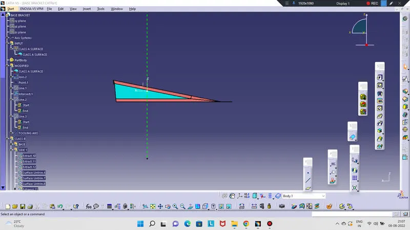
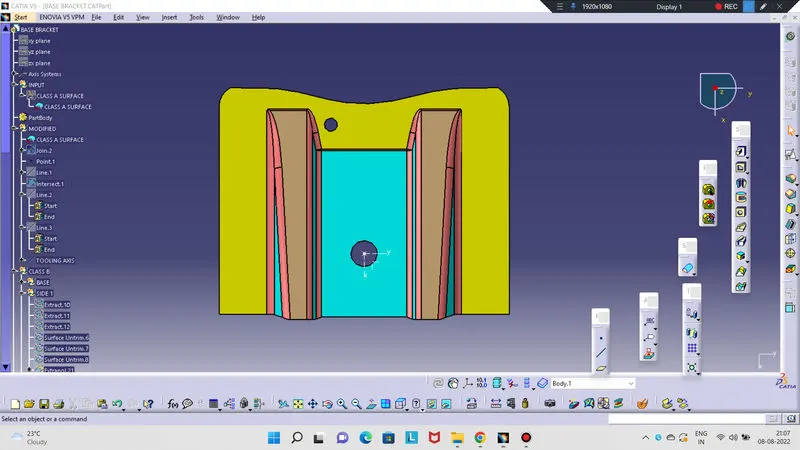
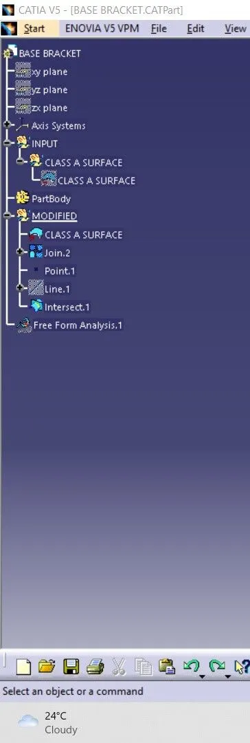
- Intersect the ZX plane of the axis system with the input and we can see that there is no surfaces that can create problem during tooling in this direction.
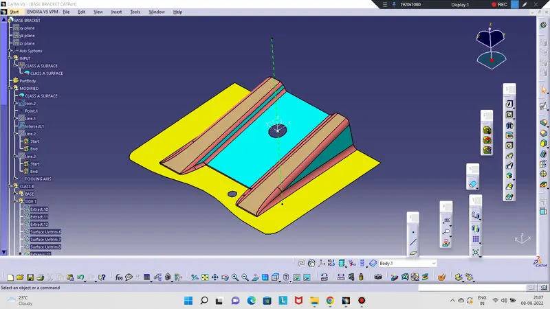
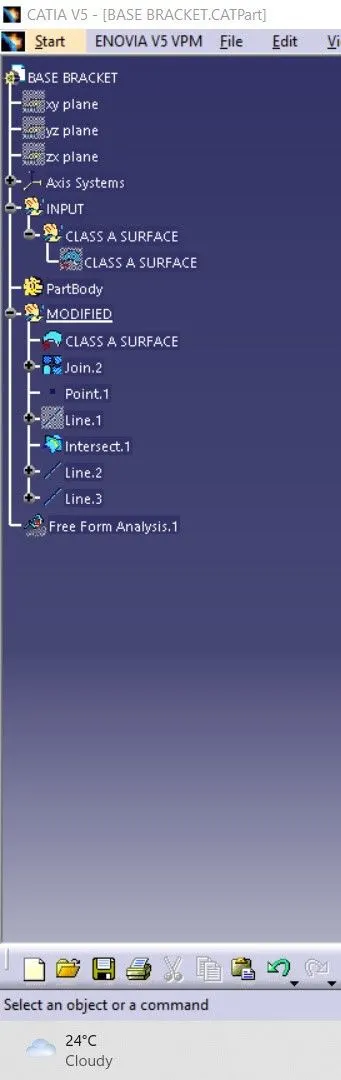
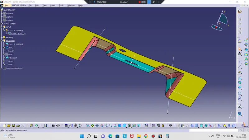
Intersect ZY plane and we are unsure of these two surfaces, so we make a line and bisect them both and this will be out tooling axis which, not so surprisingly, is the same as our guessed tooling axis. 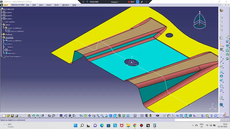
DRAFT ANALYSIS:-
- Go to insert<analysis<feature draft analysis.
- Align the tooling axis with the compass.
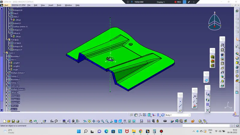
- click on the surface and see that the surface is within the permissible limit of the draft values.
- The surfaces should be green and in the column, the proper value (3 Deg) should be inserted.
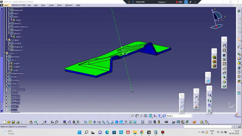
FOR CLASS-B SURFACE:- We can divide the surfaces as shown below. Then we will work on them one by one.
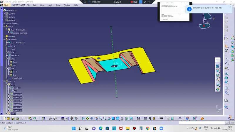
FLAT SURFACES:-
- Extract the flat surfaces
- Un-trim the surfaces.
- Extrapolate it.
- Offset it by 2.5mm
SLANT THICKNESS:-
- Extract the slant surface.
- Un-trim the surface.
- Extrapolate it.
- Offset it by 2.5mm.
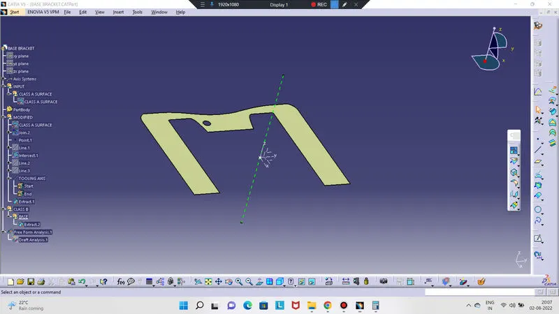
RIBS SURFACES:-
- Extract the rib surfaces
- Un-trim the surface.
- Extrapolate it.
- Offset it by 2.55mm
- Trim to get the desired shape.
- Repeat it with the second rib too.
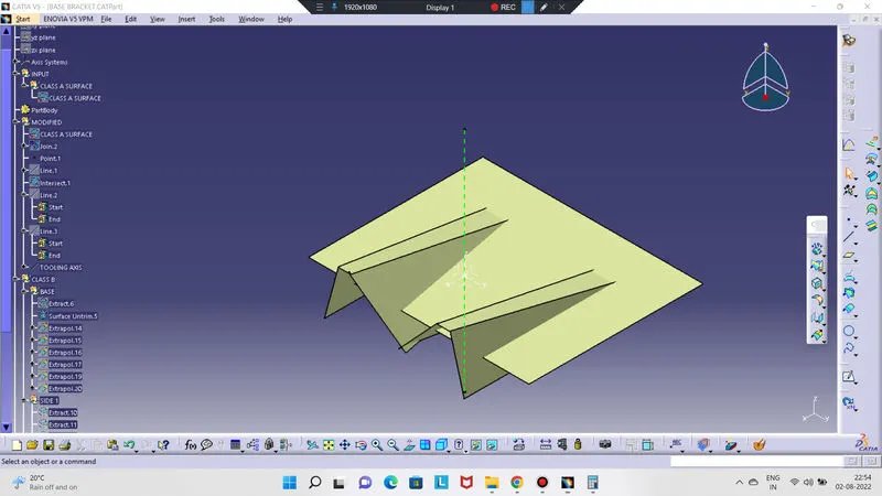
Once we have finished doing this we have to trim the surfaces to get the exact shape of the class A-surface (Without fillet) below 2.5mm. After the trimming part is done, fillet the model. The formula for filleting=fillet value+thickness (if the surfaces are below). We get our class B-surfaces
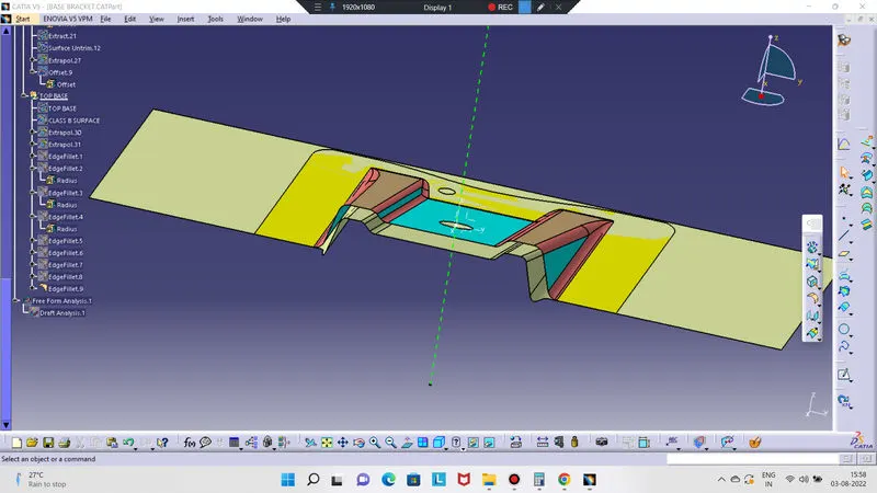
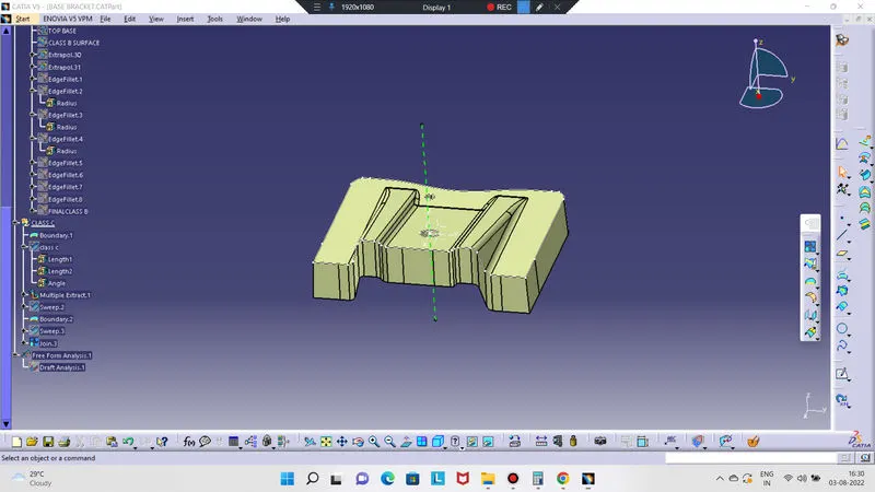
FOR CLASS-C SURFACES:-
- Extract the boundary of the class-A surfaces
- Extract the boundary of the holes on the class-A surfaces
- Use the sweep command on the boundaries one by one to get the class c-surfaces
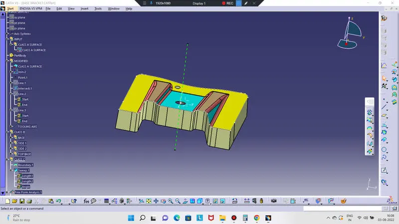
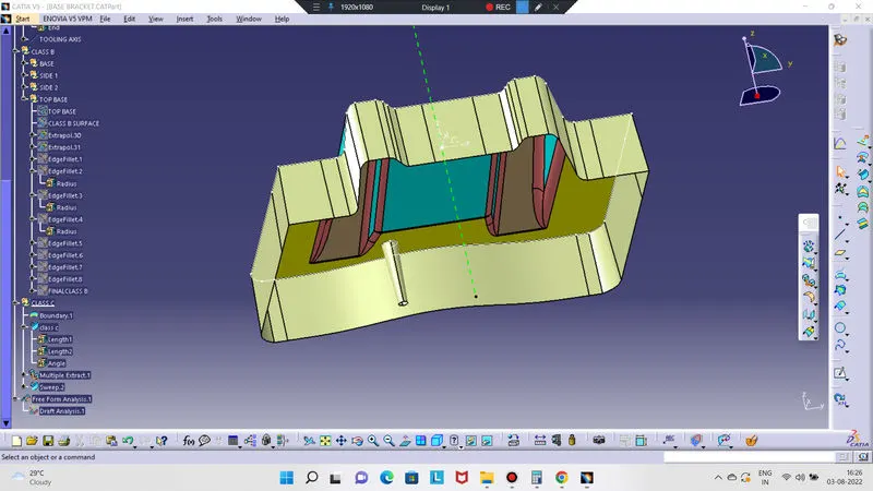
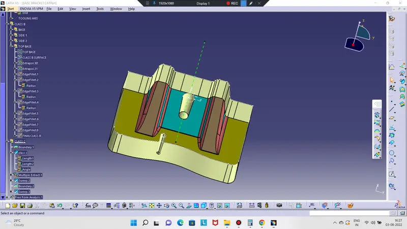
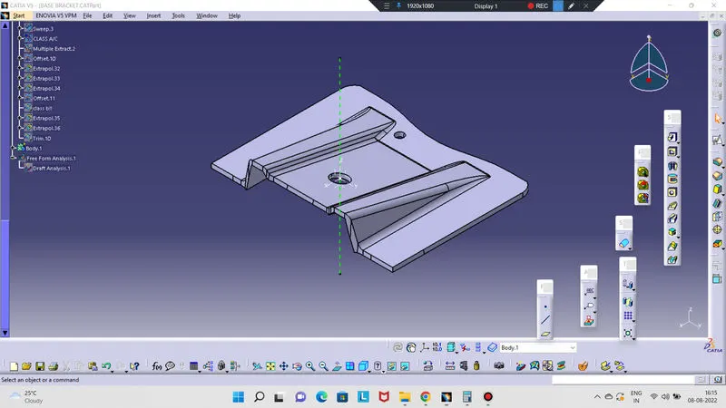
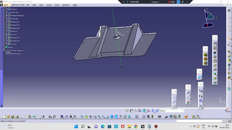
FINAL BASE BRACKET:-
- Join the class-A and class-C surfaces together.
2. Go to part design and close the model
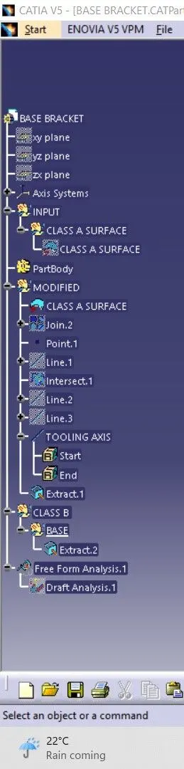
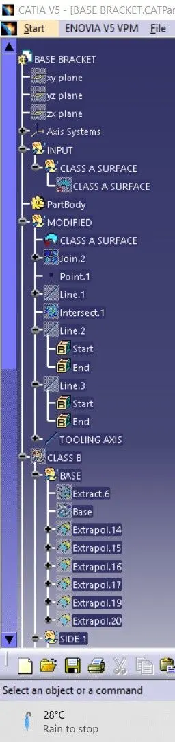
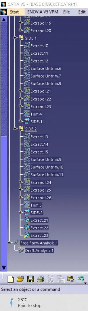
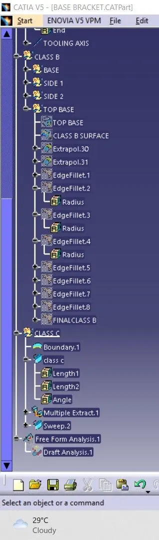
TREE STRUCTURE:-