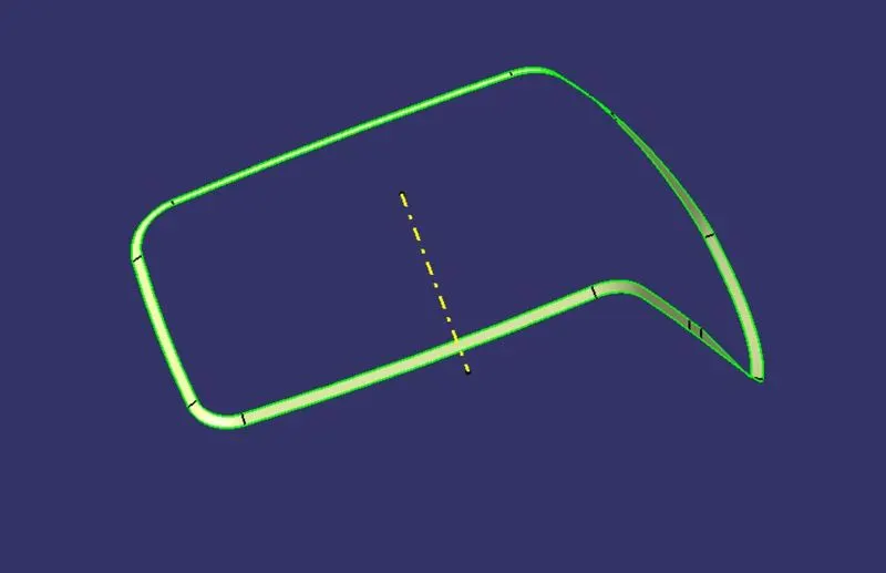
Week 8 - Challenge 2 - Switch Bezel Design
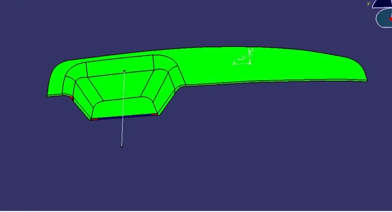
Create the Switch Bezel Plastic component through the given Class-A surface. To begin with, the tooling axis for the given Class-A Surface should be created meeting the requirements of the draft angle and at the end perform the Draft analysis on the model.
Take the Thickness of the component to be 2.5 mm
AIM
To be able to create solid from the given Class-A surface, by considering tooling axis and draft analysis.
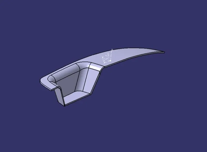
Class-A surface given:
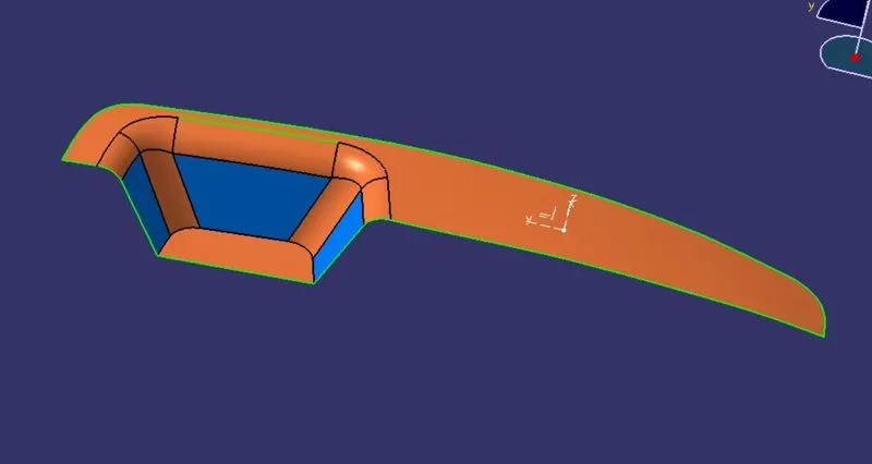
A point was created at the center of the large circle, Using that axis system is inserted,
Tooling Axis:
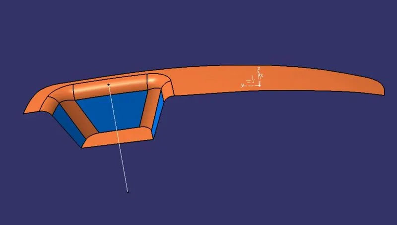
tooling axis is created by help of base plate
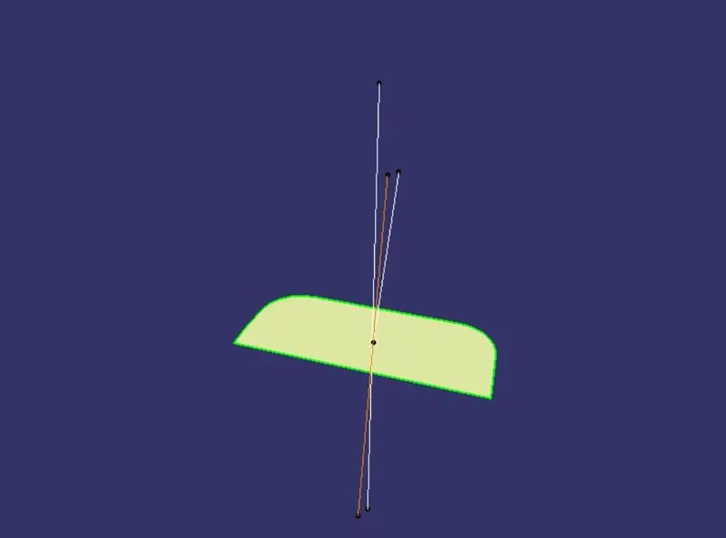
Creation of Class B:
- Now for Class B creation, we have extracted surfaces from Class A and untrimmed them to obtain the original parent surface.
- These surfaces are then offset to the required thickness.
- After offsetting, all the surfaces are trimmed into the required shape.
- Required fillets are given to the surfaces.
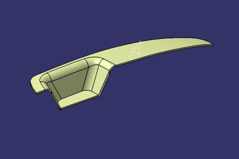
HOW THE B SURFACE IS CREATED IS SHOWN BELLOW
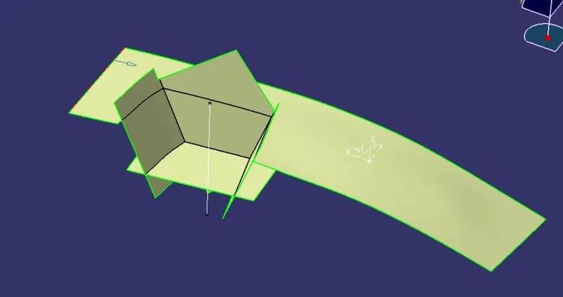
BOTTOM PLATE, SIDE WALL AND TOP PLATE IS SHOWN
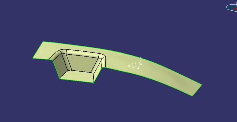
Creation of Class C:
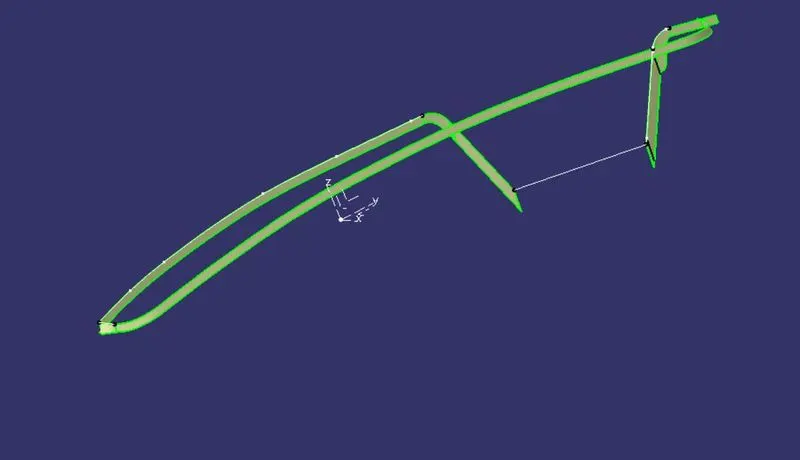
number of sweep command is used to create this class c surface
class c created with the help of sweep
and show bellow
also encure that class c should be pass 3 degree of draft angle
complete A, B, AND C are shown in join
use the Close Surface feature to make a
solid body also shown bellow
to create solid body closed body command are use to create this part
solid body from the surface.
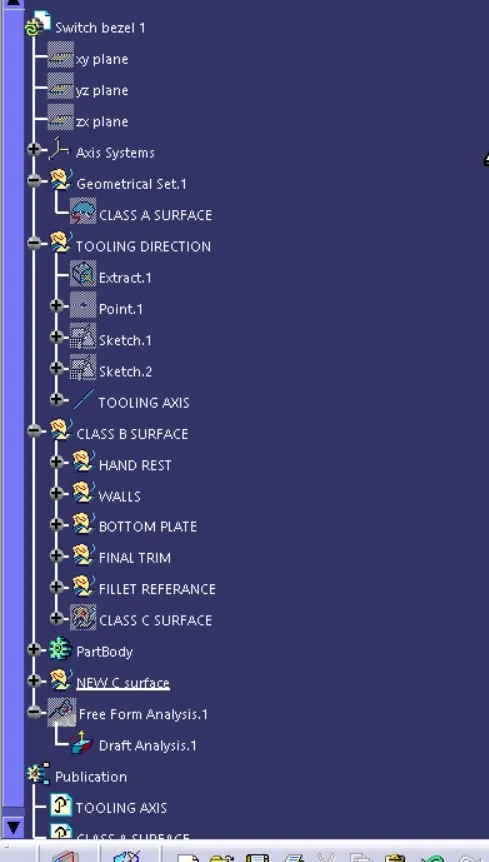
- Tree Structure
draft analysis
Creation of Class C: