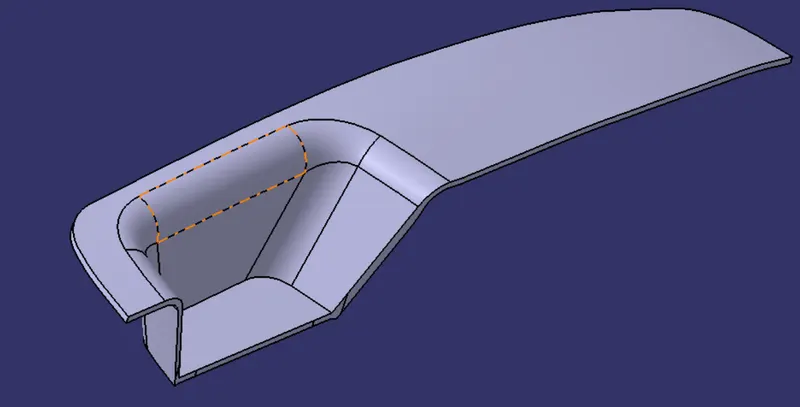
Week 8 - Challenge 2 - Switch Bezel Design
Input:
The input was given as Class A surface.
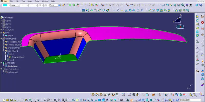
Tooling Axis:
ake a cut section of class A surface and draw two coincidence lines to that cut section. Draw an another line which bisects that two inclined lines. Here we will get first line of tooling axis.
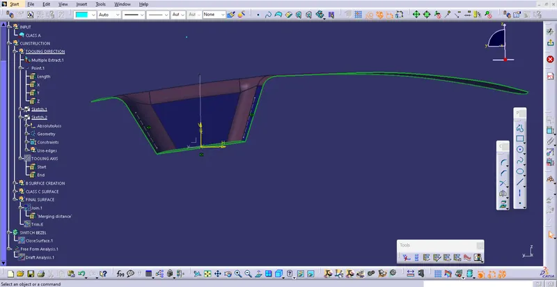
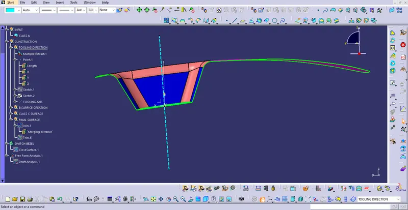
Draft Analysis of Class A:
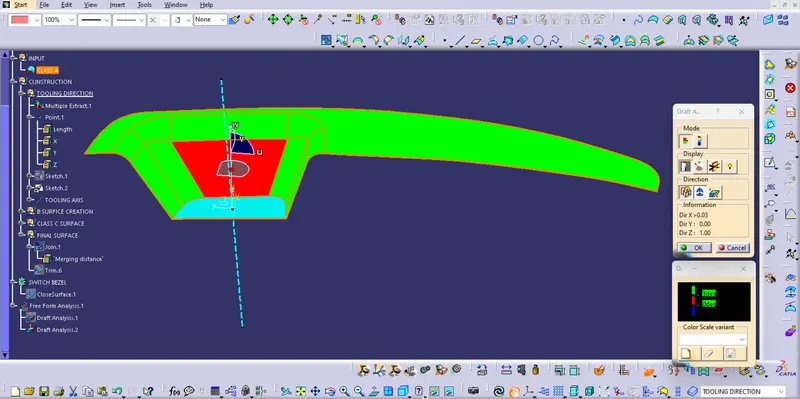
Draft analysis is done on the Class A Surface with respect to the Tooling Axis created.
Class B Surface:
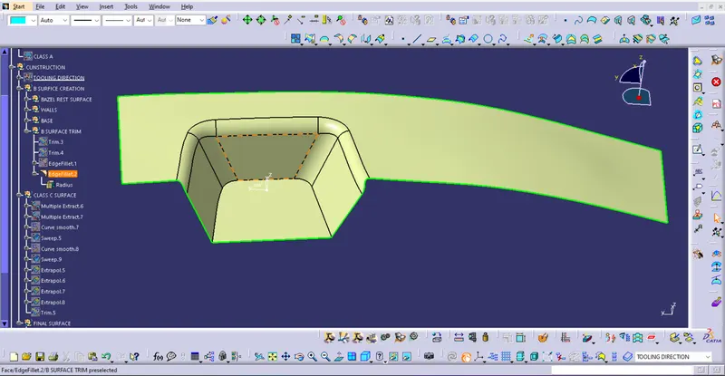
Class C Surface:
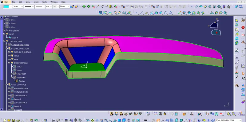
FINALSurface:
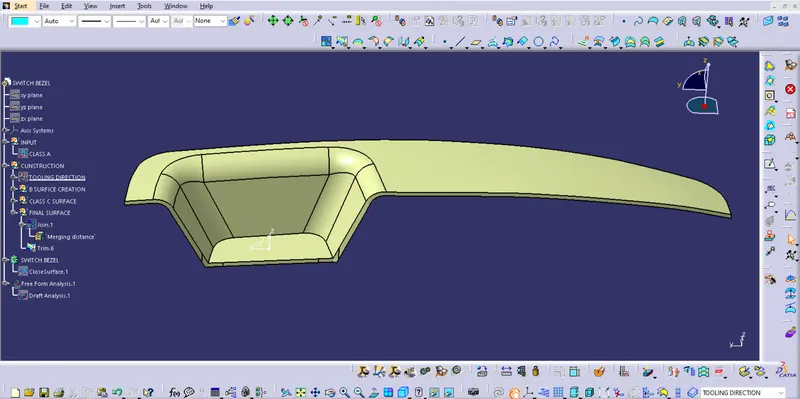
Part Body - Switch Bezel:
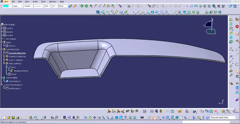
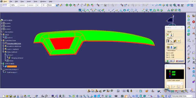
Draft analysis of the Component:
After completing the solid model go to draft analysis click on use the compass. Drag the compass to the tooling axis line as shown in figure. Then click on lock. Then click on any point of surface.
Publication:
During this process of designing the base plate, The Objects which are used frequently are published for ease of operation. Published Objects are,
- A Surface.
- Tooling Axis
- B Surface
- C Surface
- FINAL Surface
Different 3D Views of a Component
TOP VIEW
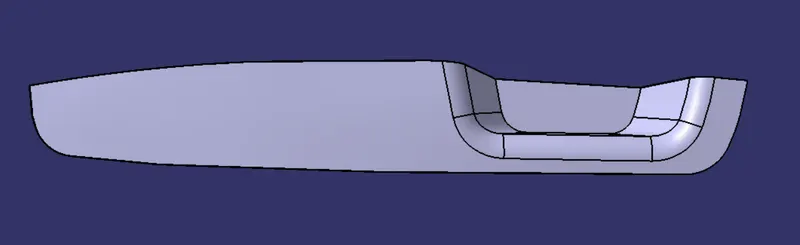
BOTTOM VIEW
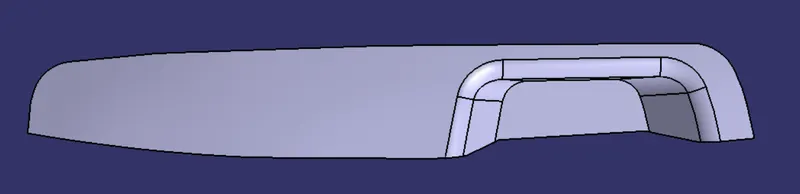
SIDE VIEW
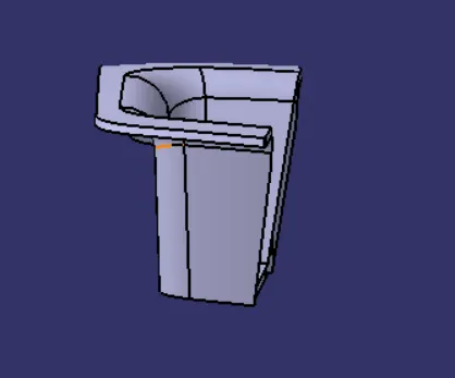
FRONT VIEW
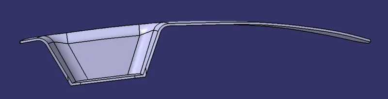
ISOMETRIC VIEW