Week 8 - Challenge 2 - Switch Bezel Design
Draft analysis :
The draft analysis technique is used to analyze whether our part model created in CAD is manufacturable based on the draft condition applied. Steps to do draft analysis.When a plastic component is made, we can observe that there is a draft angle given on each side from the base. This is because in the criteria of making a plastic material the mold should release the material when finished, if the mold surfaces are 90 degrees the material won't release from the mold because of friction due to contraction of material when cooled and may get many difficulties in the production.
To resolve this problem we maintain a standard rule to design the plastic mold or die's in such a way that there is no problem while ejecting the plastic component. So a minimum of 3 - 10 degrees of draft angle is given to every plastic component while designing.

Tooling axis creation
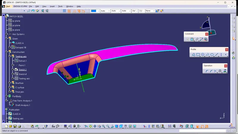
The direction in which the mold or core and cavity opens is called as tooling axis. Tooling axis is created by using bisecting method.
Step1:
The intersection is created directly in a sketch by using intersection option, were created by simply using intersection tool
Step 2:
The lines are drawn by taking the intersection lines as references. Just make sure to select the two points as a line type.
Step 3:
The two lines were drawn by simply selecting the two points.
Step 4:
The tooling axis is created by using the line tool, just make sure that to select the bisection option as a line type.
Step 5:
Bisecting lines are drawn by simply selecting the lines which are drawn above and the middle point.

Creation of Class - B and Class - C surfaces
Extracting the class - A surface without the fillets and then untriming and extrapolateing them to join them, and after that offset the surface to 2.5 mm thickness which forms as the Class - B surface and then filleting the edges to 12 mm

Class - C surface
By extracting the boundary of the class - A surface, the surface required for the class - C is obtained using the smooth curve option a smooth surface can be obtained by sweeping the line towards the direction of the tooling axis.

Triming and joining the all the class surfaces together

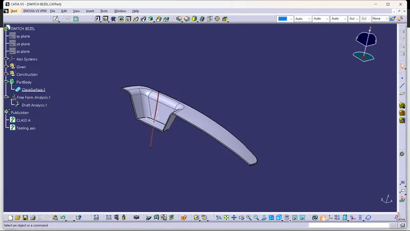
Final product out put

Final product after close surface is obtained

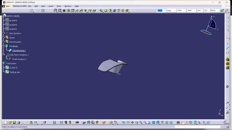

Draft analysis for final product:
