Week 10 - Challenge 1- Attachment Feature Creation (Ribs & Screw Boss)
DRAFT ANALYSIS :
Draft:
For molded or cast parts, the draft angle is the amount of taper perpendicular to the parting line. It is measurable in degrees. Because plastic shrinks and sticks on molding surfaces as it cools, we create draft at the walls of the plastic part for smooth ejection or breaks free from the molding surfaces more easily and without dragging. To reduce the risk of damage to the parts and ensure ejection, a functional injection molding part must have drafts on both the cavity and core sides.
Nominal values for Draft angles:
- 3 Degrees is a nominal draft angle.
- 5 Degrees can also be manufactured. Increasing the manufacturing cost.
- 7 Degrees is considered for Textured surface parts.
Steps followed for Draft Analysis:
- The created part must be changed to the material mode in the display frame.
- Compass is enabled and placed in the direction of the Tooling Axis.
- The lock command is then used to fix the compass along the tooling axis.
- Colour codes are classified and Draft angle is applied.
- Running point analysis is used to display permissible draft angle.
Tooling Axis:
In injection molding, the Class A surface is first analyzed to determine the axis or tooling direction that separates the molds. Tooling direction is critical for plastic product design because it determines mold direction.
Tooling Axis Creation :
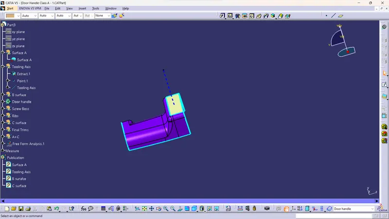
- Tooling axis here created is by selecting one of the natural axes as it clears the draft.
- Here, tooling axis is created by extracting one of the surfaces for creating a point and a new axis is created at that point.
- So, a flat face is extracted and created a point at its centre. Axis is also created at that point.
- Now, line is created using line tool and giving line type as point-direction and selected the point and direction for creating tooling axis and tooling axis is created along x direction.
Draft analysis for A Surface :
-
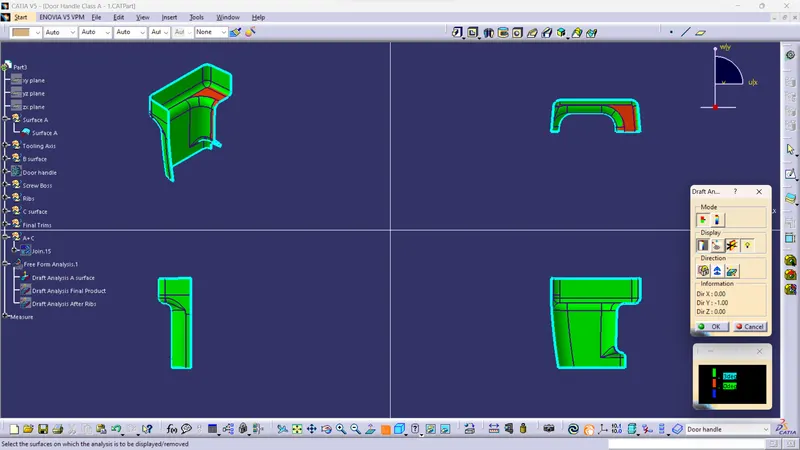
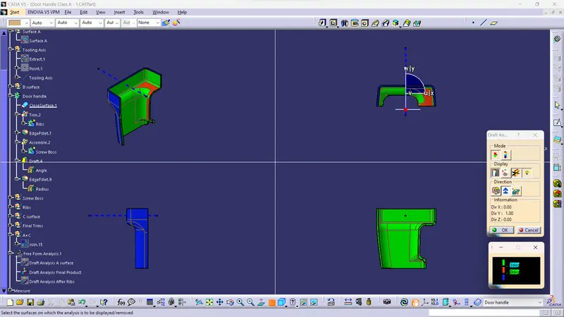
The Draft Analysis command enables you to detect if the part you drafted will be easily removed. This type of analysis is performed based on color ranges identifying zones on the analyzed element where the deviation from the draft direction at any point, corresponds to specified values.
- Before going to draft analysis go to customized view parameter >under mesh >check Material and then click ok.
- Now for draft analysis go to insert » analysis » feature draft analysis.
- Use the compasss to define the draft direction.
- In the colour scale change the draft angle to 3 degree.
- The component changes to green in indication of passing draft angle.
- Use running point to check the angle on the component.
Creation of Class B Surface :
- Extract the surfaces from the class A using multiple extract and untrim them.
- Use Extrapolate to make sure that all the untrims are properly intersected to trim and offset the surfaces to 2.5 mm to create the thickness.
- Fill the patches which are not offested by the using the commands like extract,boundary and multi-section surface.
- Then join the patches to the offseted surface using the command.So will get the complete class B.
Creation Of Class C Surface:
The surface that joins class-A and class-B surfaces are class-C surfaces.The method used for class c surface is sweep feature. Since it is a complex class-A surface, we cannot create the class-A boundary curve and sweep in a single stretch so we will create small sections using multi-extract command and then create sweep of 90 degree with reference to the surface option.
Final Product After Closed Surface :
Draft analysis for Final Product:
Rib Creation :
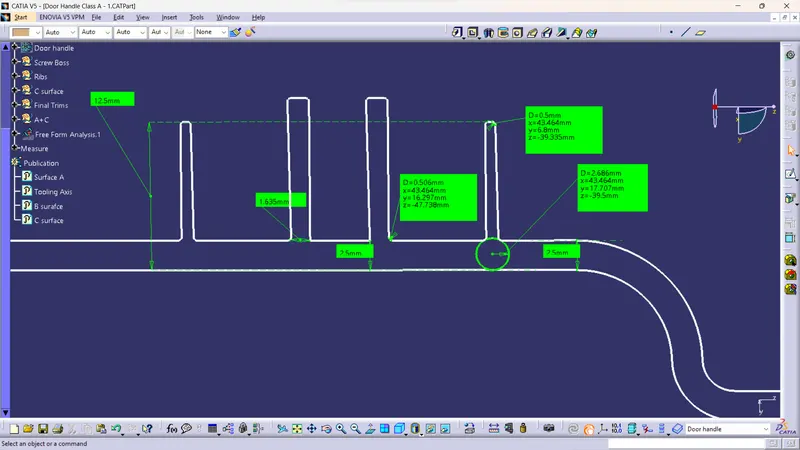
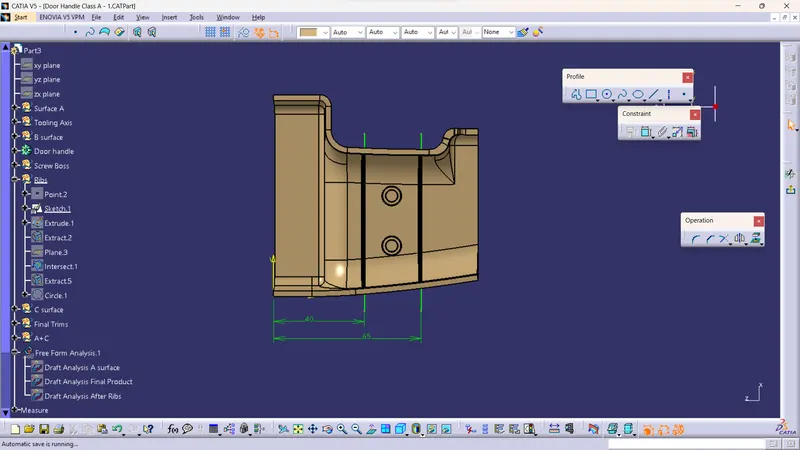
Next, the profile is extruded, to find the height,h=Wall thickness * 4
=2.5*4
= 10 mm
Therefore, the height is 10 mm
The extruded surface is thickened,
Thickness,w=0.4*t
=0.4*2.5
=1mm
Therefore, the thickness of the rib is 1 mm.
Screw Bosses Creation :
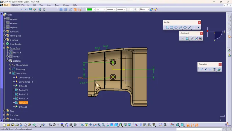
Screw Boss features are commonly found in injection molding designs. They are used to aid in the assembly of molded parts by providing a channel for a screw. Their primary use is to strengthen holes or slots in the surface present in the part model.The construction process of creating the screw boss is explained below:
-
For thickness, the design rule is as follows,
Thickness,w=0.6*Thickness of the part
=0.6*2.5
=1.5 mm
- As per the design rule, the draft given for screw boss is 0.5 deg on inside and outside of the screwboss
- Then fillet is applied to the faces of the rib. As per the design rule, the fillet can be 0.25 mm.
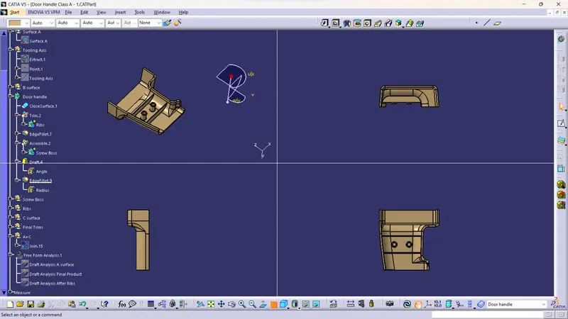
Reference of Ribs and Screw Bosses:
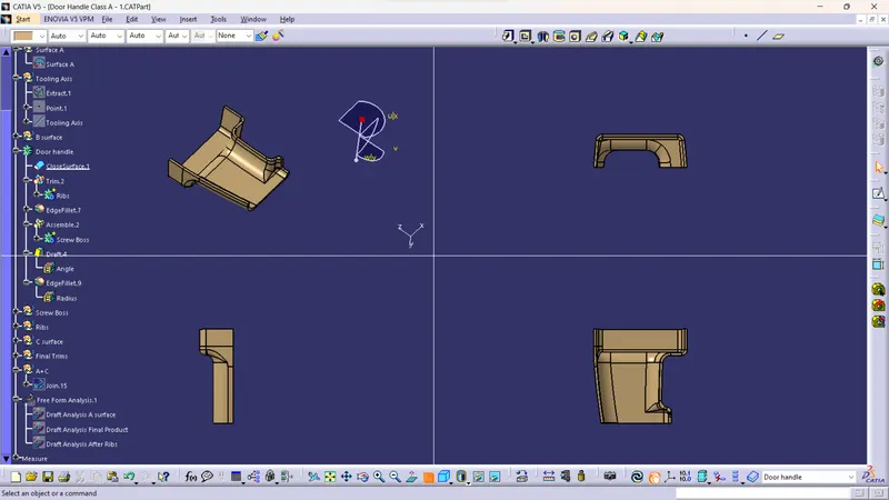
Draft Analysis After Ribs and Screw Boss Creation :
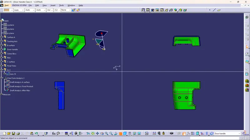
Measurements Of Ribs and Screw Bosses: