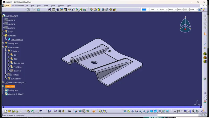
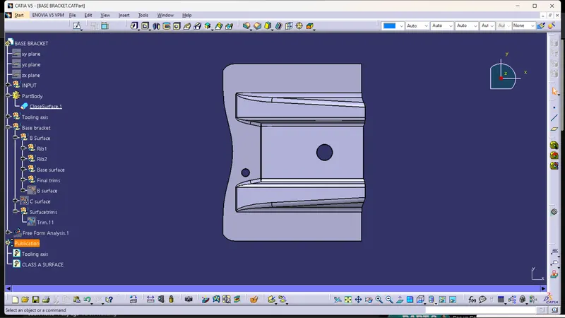
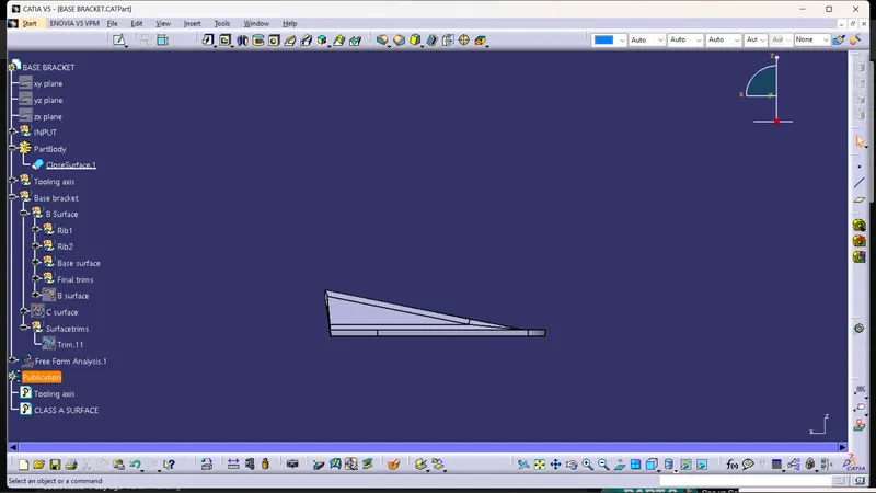
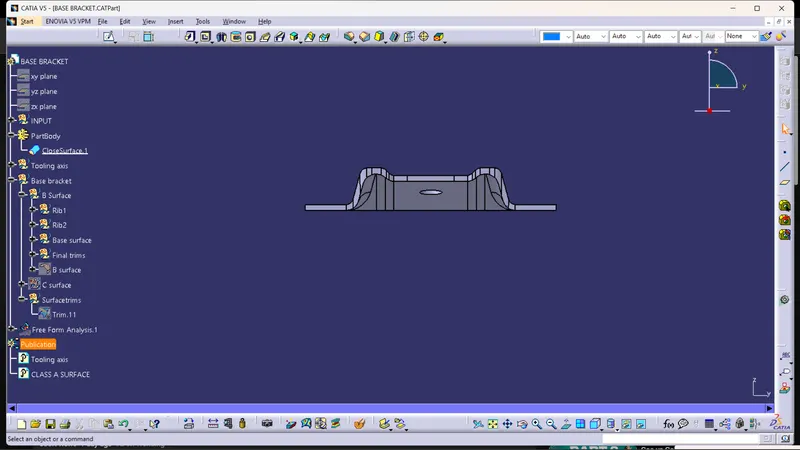
Week 8 - Challenge 1 - Base Bracket Design
Base bracket:
Tooling axis creation :
The direction in which the mold or core and cavity opens is called as tooling axis. Tooling axis is created by using bisecting method.
Step1:
The intersection is created directly in a sketch by using intersection option, were created by simply using intersection tool
Step 2:
The lines are drawn by taking the intersection lines as references. Just make sure to select the two points as a line type.
Step 3:
The two lines were drawn by simply selecting the two points.
Step 4:
The tooling axis is created by using the line tool, just make sure that to select the bisection option as a line type.
Step 5:
Bisecting lines are drawn by simply selecting the lines which are drawn above and the middle point.
Draft analysis :
The draft analysis technique is used to analyze whether our part model created in CAD is manufacturable based on the draft condition applied. Steps to do draft analysis.
Step1:
Enter the cad part
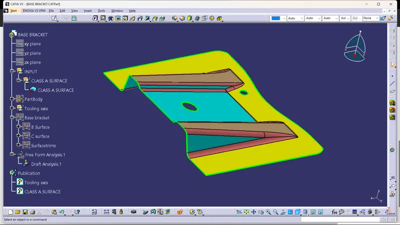
Step2:
Go to material mode and select material
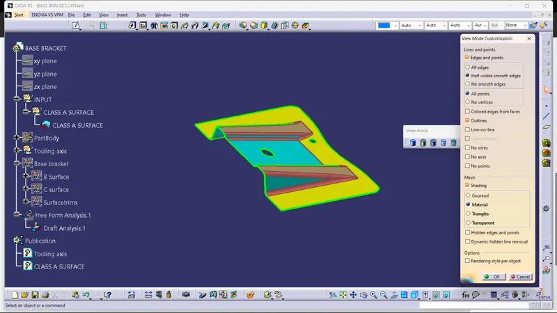
Step3:
Go to draft analysis, for further analysis.
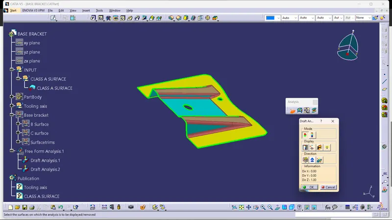
Step4 :
Create the tooling axis for the given part.
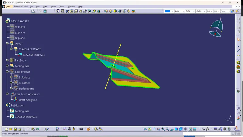
Step5 :
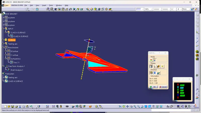
Drag the columbus to the tooling axis and measure the angle for the given part for manufacturing.
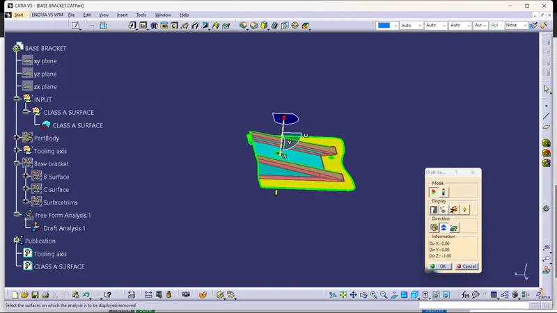
Draft analysis when the degree is correct:
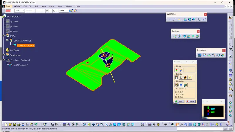
Draft analysis when the Degree doesnt satisfy:
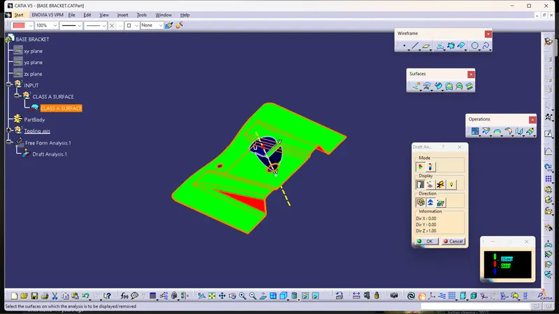
Draft analysis after the close surface :
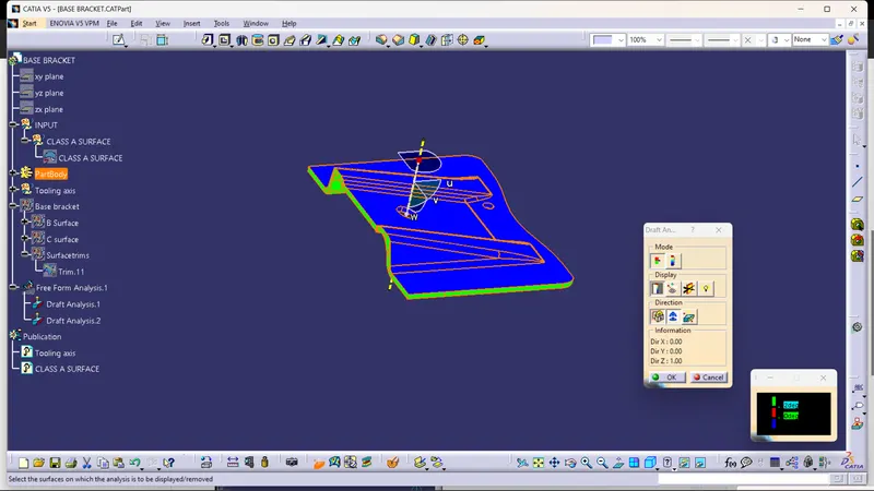
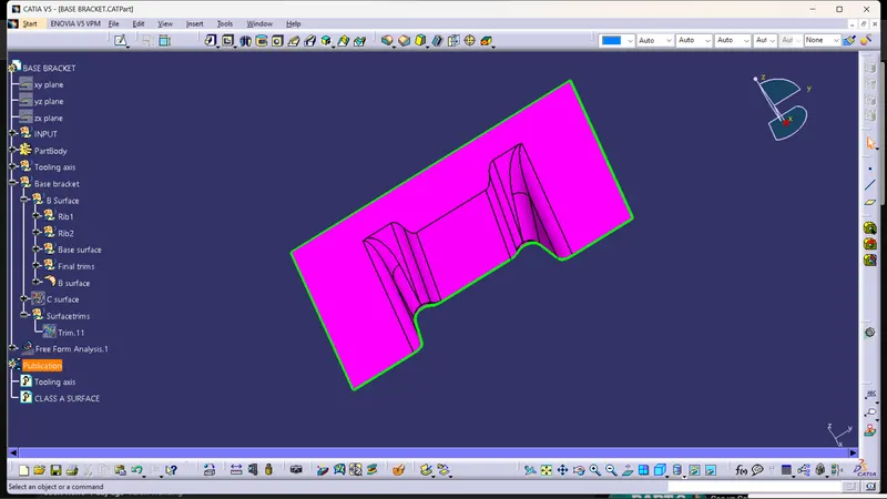
BSurface:
C Surface :
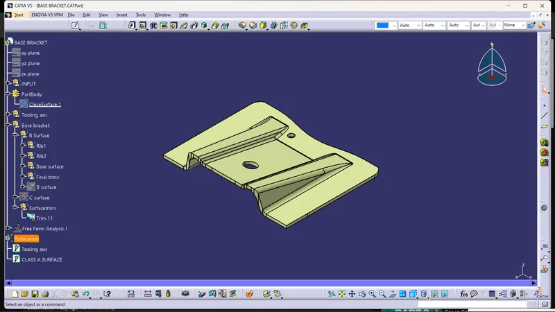
Close surface with the faces :