Week 8 - Challenge 2 - Base Bracket Design
AIM:
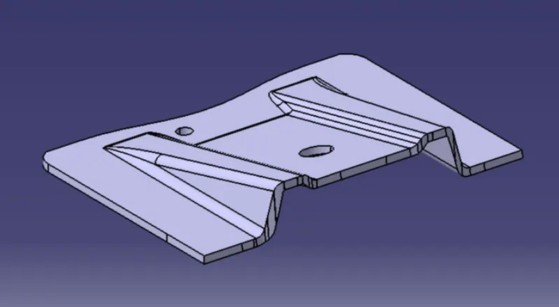
To create a base bracket component by the given class A surface and perform draft analysis.
THEORY:
CLASS A SURFACE:
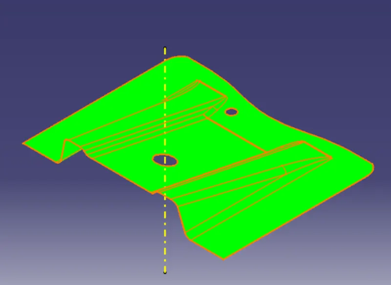
It is the outermost surface of the component with high accuracy and precision. It has aesthetic value and cannot be modofied without authorization.
CLASS B SURFACE:
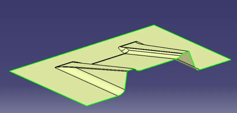
It is the inner surface of the component which we get after thickening it.
CLASS C SURFACE:
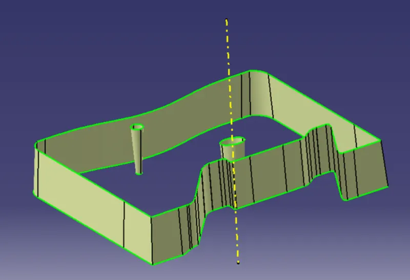
It is the surface which joins the class A and class B surfaces along the boundries.
PROCEDURE:
1.Check the boundary of the class A surface and ensure there is no gap in between the surface.
2.Create a dummy tooling axis along z-direction.
3.Create an intersect between the YZ plane and the class A surface.
4.Create reference lines with intersect produced that are almost parallel to the dummy tooling axis.
5.Create a bisecting line for the reference lines created and this line indicates the final tooling axis.
DRAFT ANALYSIS:
CLASS A SURFACE:
1.Change the view to customized view and enable the material in shading option.
2.Insert the feature draft analysis.
3.Click the compass icon and place the compass along the tooling direction.
4.Lock the draft direction and select the component to the draft.
5.Enable the color scale and change the draft value.
CLASS B SURFACE:
1.Extract the individual surfaces form the class A surface.
2.Untrim the extracted surface.
3.Offset the extra ploted surfaces inwards to get the thickness of the component.
4.Trim the offset surface and give fillets as required to get the class B surface.
CLASS C SURFACE:
1.Create the boundaires for the class A surface.
2.Sweep the boundaries along the tooling direction with required draft angle to get the class C surface.
OUTPUT:
1.FINAL OUTPUT:
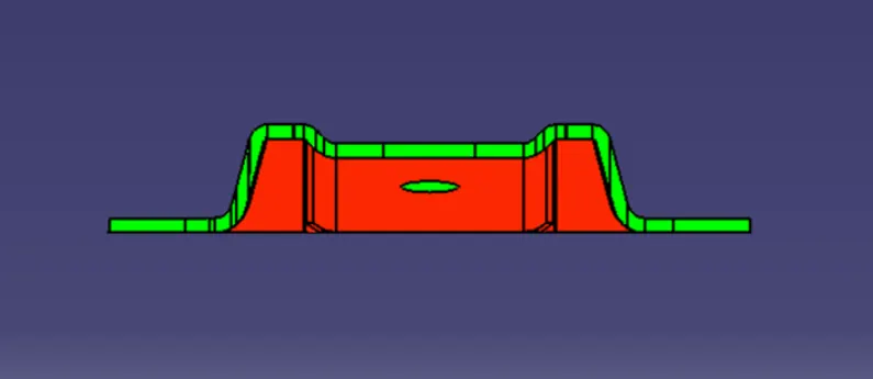
2.FRONT VIEW:
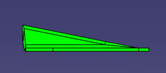
3.SIDE VIEW:
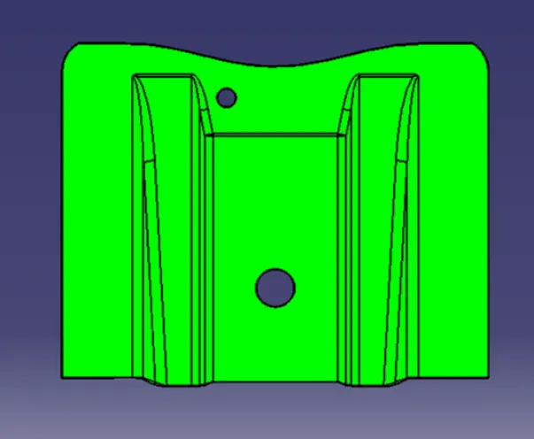
4.TOP VIEW:
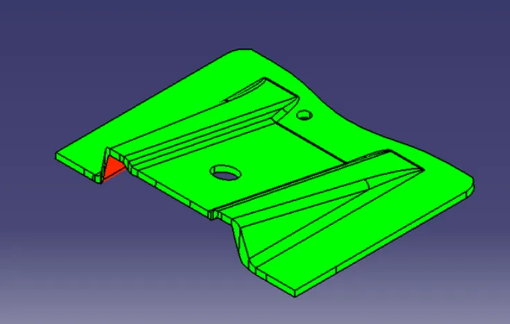
5.ISOMETRIC VIEW:
RESULT:
Thus the base bracket component by the given class A surface and perform draft analysis is performed sucessfully.