Week 8 - Challenge 2 - Base Bracket Design
Automotive Plastic Design using CATIA V5
Aim: To Create the Base Bracket Plastic component through the given Class-A surface. To begin with, the tooling axis for the given Class-A Surface should be created meeting the requirements of the draft angle and at the end perform the Draft analysis on the model.
Procedure:
- First import the surface or the CLASS A model to the CATIA V5.
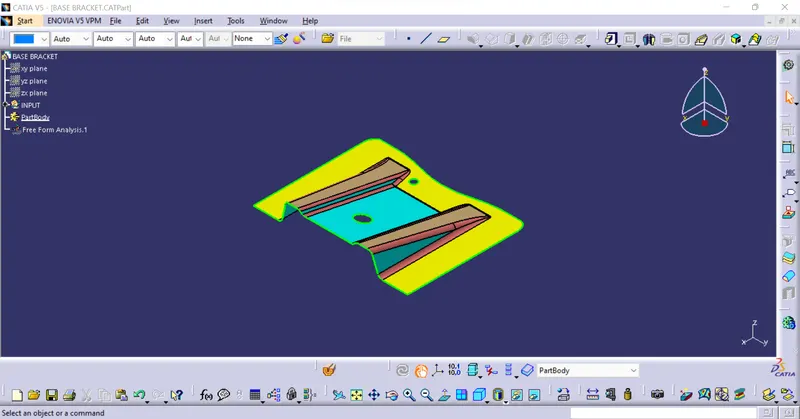
- As the plastic bracket is a surface model we have to open it in the GENERATIVE SHAPE DESIGN which is observed in START << SHAPES.
- We have to check the Connectivity of the Class A surface which we have uploded.
- Ensure that there are no gaps between the surfaces on the class a surface.
- Now Identify the direction to create the tooling axis.
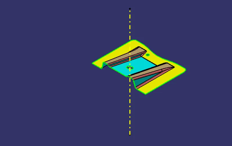
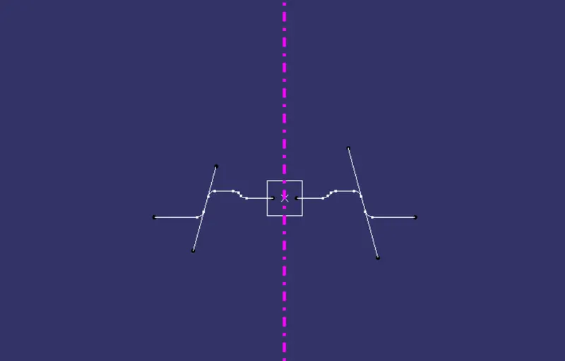
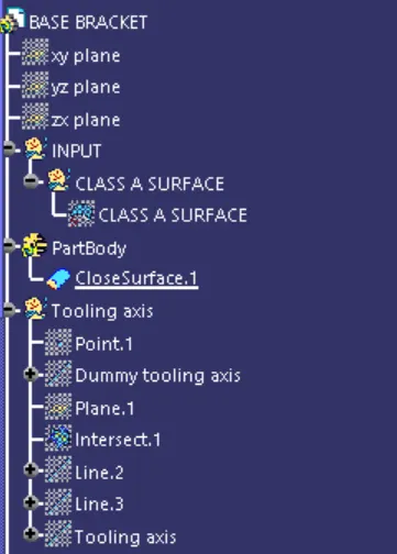
- After identifing the direction we have to create a Dummy tooling axis by creating a line along z diection , point and plane.
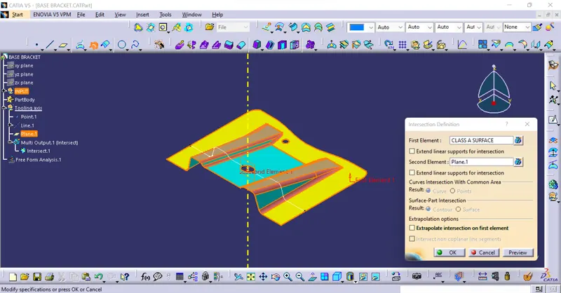
- Using the INTERSECTION command create the intersection along respective directions.
- Now, Observe the model and find out the surfacing which are creating the problems for Draft Analysis.
- Creat the supporting lines along the directtions by using the point to point option in line command.
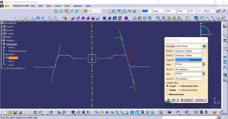
- After creating the supporting lines,Create bisecting lines using the supporting lines.
- The bisecting line which is created will be the TOOLING AXIS.
- Finally the TOOLING axis is created and by using this we have to do the draft analysis on the surface.
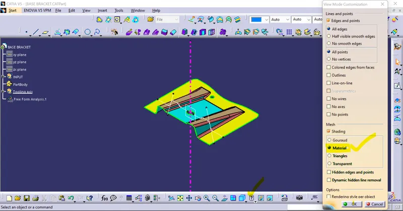
- Before doing the draft analysis we have to set the material mood for the we have to change or customize the view parameters and select material.
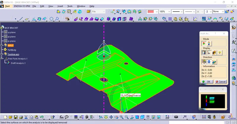
- To do the DRAFT ANALYSIS we need to go to INSERT
- In Feature Draft analysis we have to first use the COMPASS option and define the new current draft direction.
- Set the DRAFT angle as 3DEG.
- LOCK the direction and analize the Draft under the running point on the surface .
- To ensure the draft is perfect just switch to quick analysis mood.
- Finally the draft analysis on the Plastic Base Bracket is done.
- Now we have to Apply the thickness for the bracket or class A surface.
- For that first we gave to create a B surface in a new geometrical set .
- Observe the class A surface and find the the main surface apart frim the fillets. in our model we have 3 main surface those are the base surface, inclined surface and the ribs.
- Lets work on ribs first,
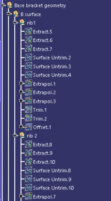
- Create a new geometrical set and name it as Rib 1 and Rib 2.
- Then extrace the surface from class A surface then un trim the ectracted surfaces , after un triming extrapol the surface and then trim the extra surface by comparing with class A surface
- And finally off set the surface with the thickness of the model.
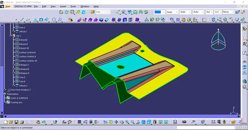
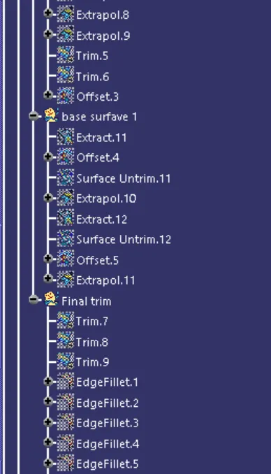
- Do the same for the other rib , base and inclined surface on the model.
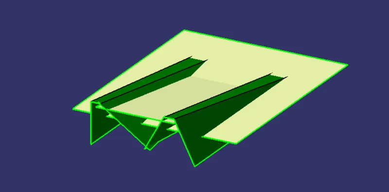
- Now, we get the total surface by appling the fillets we get the B SURFACE fo the model ( be care ful when appling the fillets measure the class A fillet radius and add the thickness to it to get the equal distance between the surfaces)
- The B SURFACE is formrd after the fillets are given.
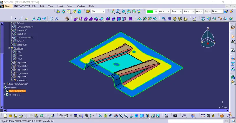
- Now, we have to create the C SURFACE, for that first we have to create a new geometrical set.
- From Class A surface select the boundries , and then use the sweep command to create the C surface ( in sweep select the sweep as with draft direction)
- We use the Tooling Axis which we have created earlier to create Class C surface.
- Make sure you give the draft anglr and draft direction corretly.
- Therefore, the C SURFACE is created.
- DO the same for Holes.
- Now join the Class A and C Surface .
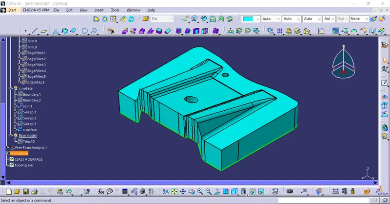
- After joiningn A and C surfaces trim it with class B surface to get the Base bracket Surface model.
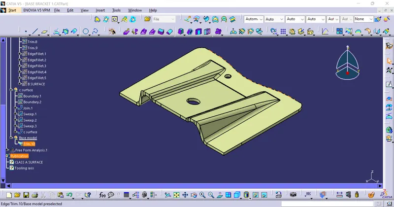
- Now, we have to form a solid model from the surface model. For that we have to move to part body and choose a commed called close surface and select the surface
- Finally we get the solid model of the base bracket .
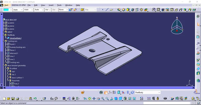
VIEWS:
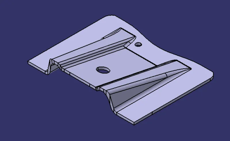
ISOMETRIC VIEW:
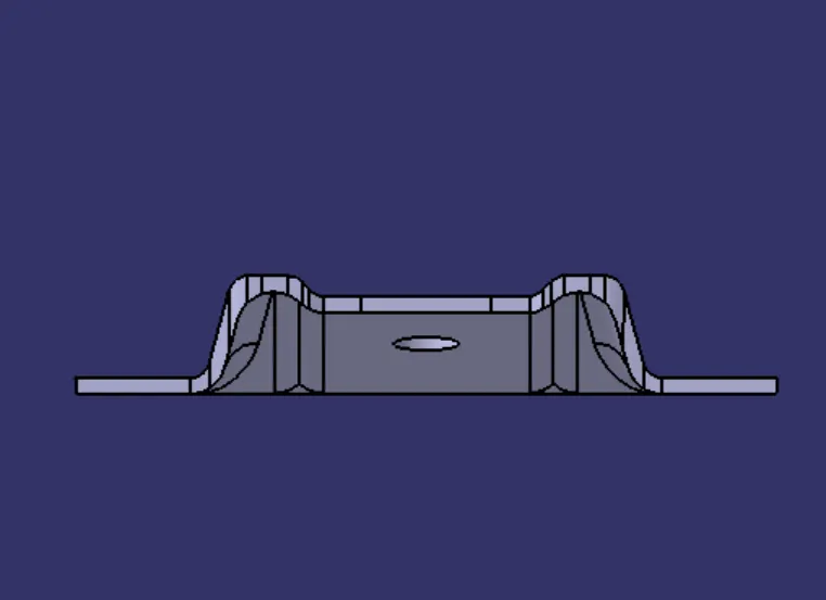
FRONT VIEW:
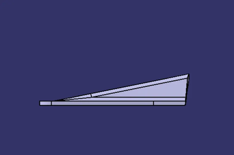
SIDE VIEW:
TOP VIEW:
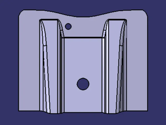
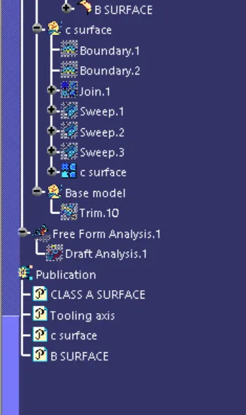
TREE:
Conclusion: Finally. we Created the Base Bracket Plastic component through the given Class-A surface. first we created the tooling axis for the given Class-A Surface by meeting the requirements of the draft angle and at the end we performed the Draft analysis on the model.