Week 8 - Challenge 2 - Base Bracket Design
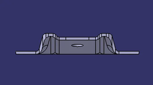
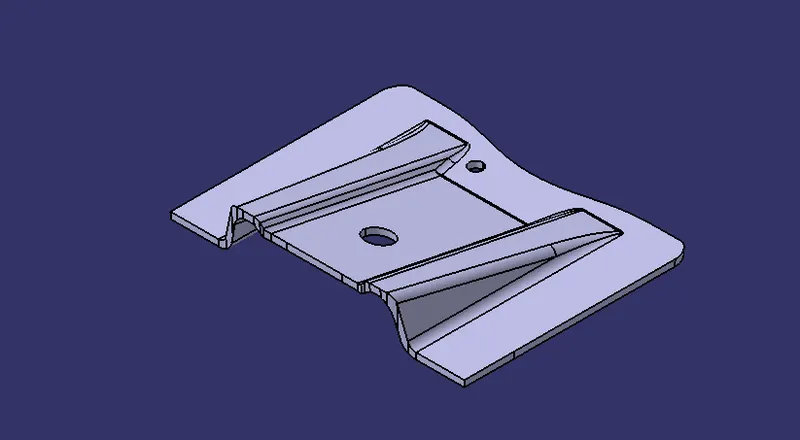
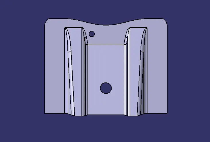
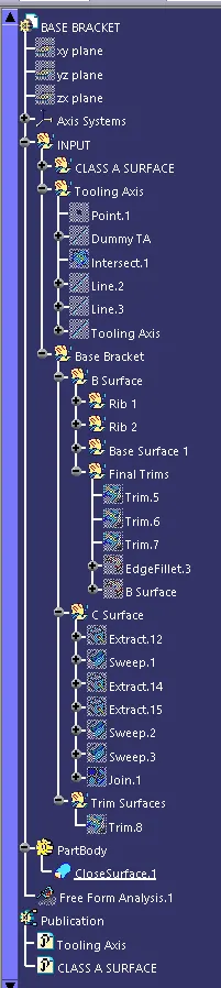
Tooling Axis Creation -
1.
For creating the tooling axis we followed certain steps to ensure the axis is correct. Initially we se for any gaps in the sloid or the class A submission by either creating a join and analysing it or by creating a boundary for the element so we get to know if there are any openings.
2.
We then Go ahed and analyse with our understanding and visual data so where could be the tooling axis be placed regarding the three axis X,Y and Z respectively once decided we create a dummy axis which could be used as a reference for creating our tooling axis.
3.
Then we go ahed and intersect the part along the palnes one by one which created a outlined view of the surface we are working with in the given bisected plane .
we select the lines or edges then extend to a degree where it is easily usable and then we introduce a line bisecting the two expanded lines giving us a middle line for the following two angled lines.
Further this step is re applied to other planes too where it can be intersected and then the tooling axis for the given planes are present for us to work on seperately.
4.
We then finally bisect the two tooling axis of the planes too getting out final Tooling Axis which is required so as to manufacture the part along a axis of movement for mold.
Draft Analysis -
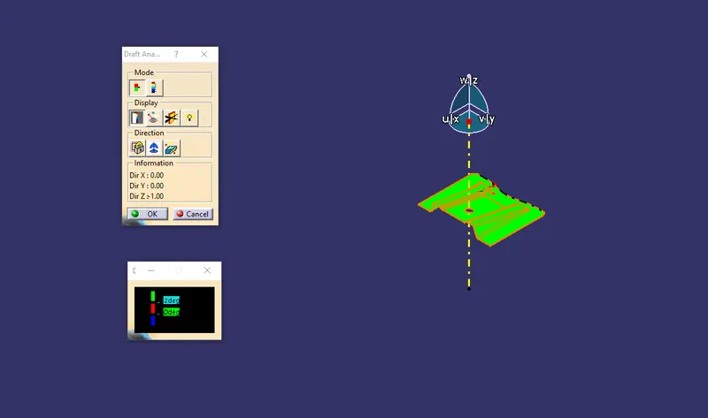
For Draft analysis we go to Insert - Analysis - Feature Draft Analysis
Make sure the View parameter is on customise - Material
Click on the Compass Icon and bring that to the tooling axis ang get it allined as per requirement
We have a small popup stating colors for the specific draft angles and the colour of the component too changed to one of them showing the draft angles.
By clicking on the icon we can also check angles on specific surfaces,
Thus, Draft analysis is Concluded.