Week 8 - Challenge 2 - Base Bracket Design
AIM:
Create the Base Bracket Plastic component through the given Class-A surface. To begin with, the tooling axis for the given Class-A Surface should be created meeting the requirements of the draft angle and at the end perform the Draft analysis on the model.
INTRODUCTION:
1. Class A surface: A surface that is given to the plastic modeler which is of aesthetic and outermost surface. The surface made by the designer is known as a Class A surface.
2. Class B surface: A surface that is below the Class A surface, at a certain thickness, which contains engineering aspects on it is known as Class B surface.
3. Class C surface: A surface that joins the Class A and Class B surface is known as a Class C surface.
PROCEDURE:
1. Creating a tooling axis
2. Performing draft analysis
3. Creating a Class B surface
4. Creating a Class C surface
5. Creating a solid model
Step1: Creating a tooling axis:
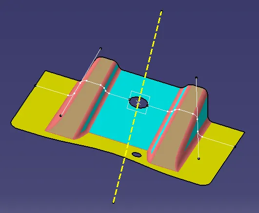
Initially observe the class A surface and check whether the model contains any discontinuity and check joined properly or not. Check
the model in all directions. Since there is only one possibility, we can go with the top plane and create an axis
(x,y,z direction)
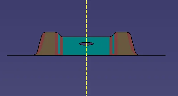
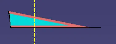
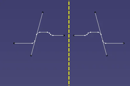
Creating an intersection at the required position. Creating a dummy tooling axis. Create two lines at the required intersection and
bisect a new line with the previous two lines. Therefore we get a
Extracting the surfaces due to fillets are present and offsetting them for a 2.5mm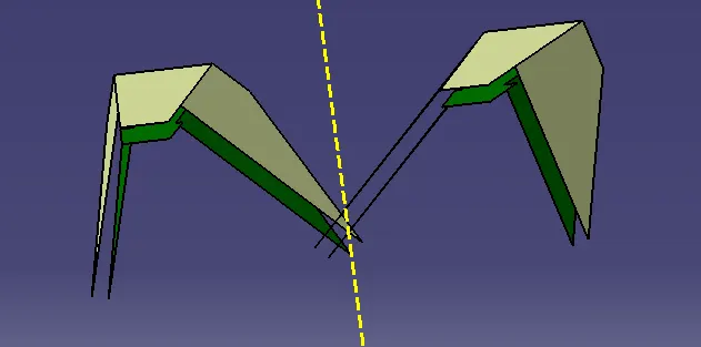
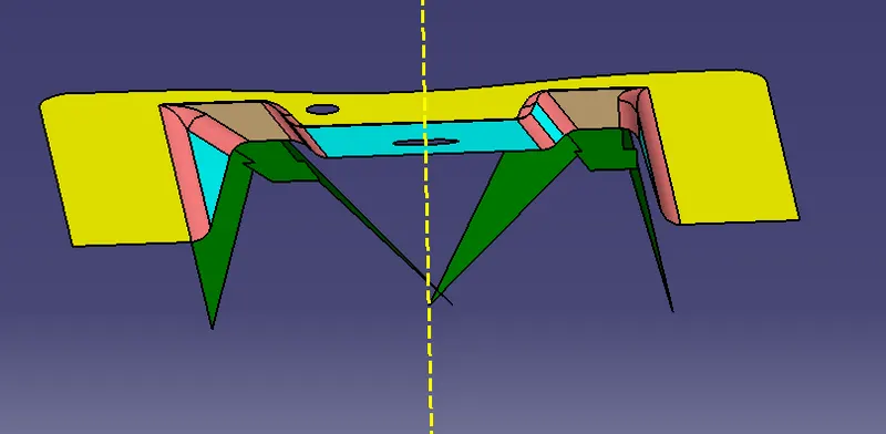
OFSETTING THE BASE SURFACE
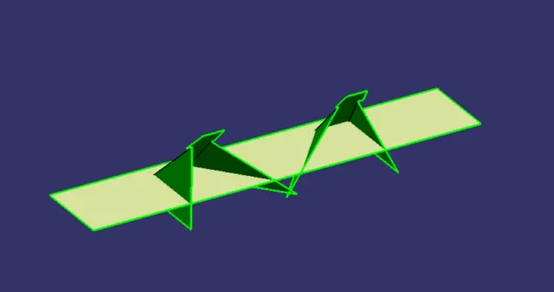
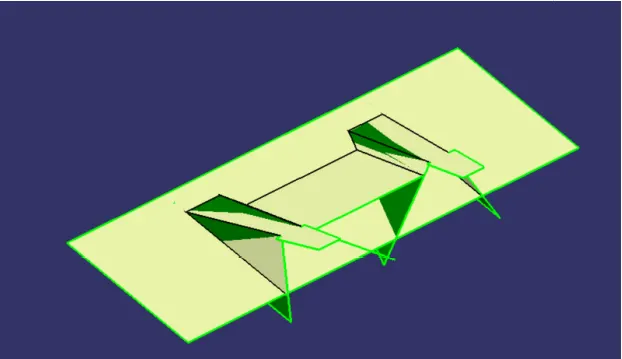
After all the offsets, trimming and applying fillets are done for the required shape. Hence the class B surface is done
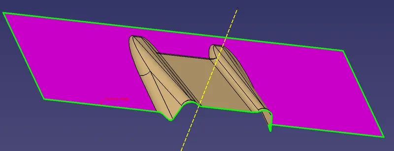
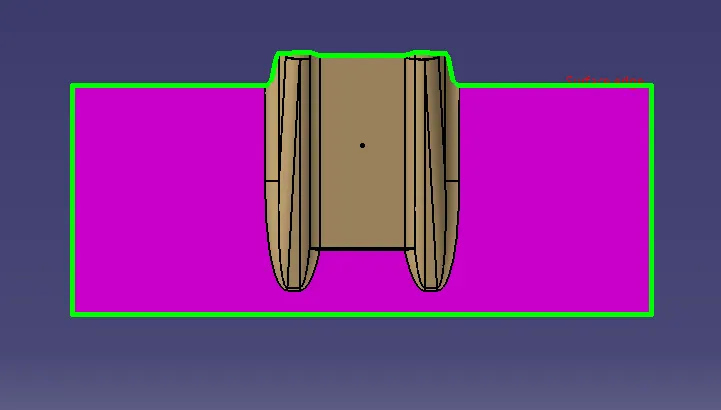
Extracting the outer boundary and joining with the class B surface. Therefore the Class C surface is formed.
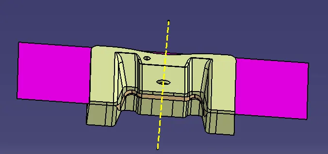
Trimming all the unwanted surfaces and maintain the model without any gaps
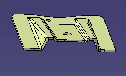
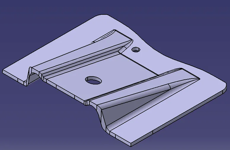
the soli body is created using the close body method
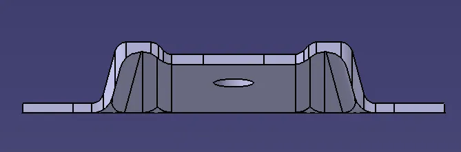
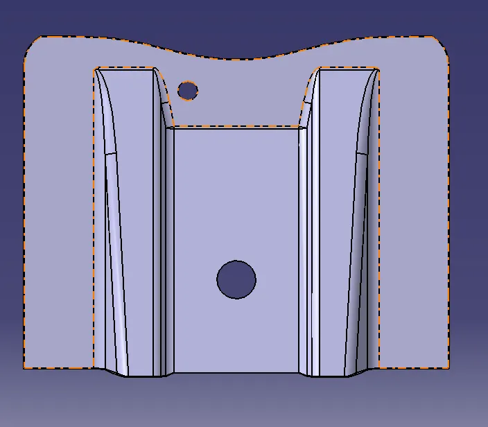
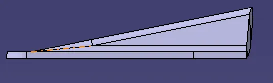
all views of the solid body
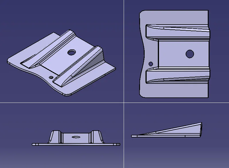
isometric view:
front view:
top view:
side view:
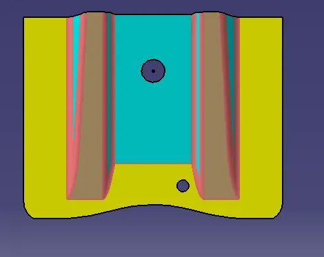
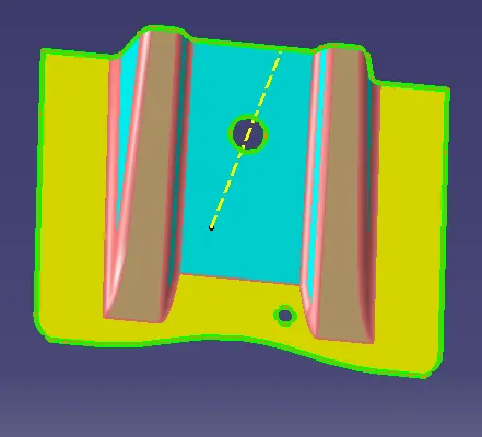
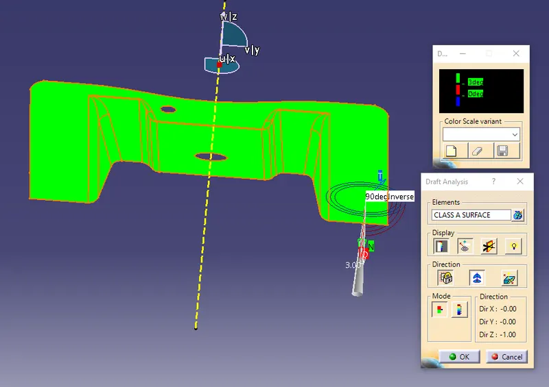
DRAFT ANALYSIS:
draft analysis for a class -A surface
draft analysis for a solid model created using the class B and class C
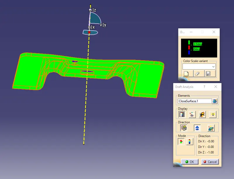
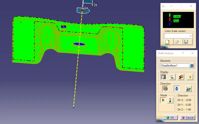
the draft angle of 2.6 is positive for the class c surface
the blue colour indiactes the holes are in reverse direction
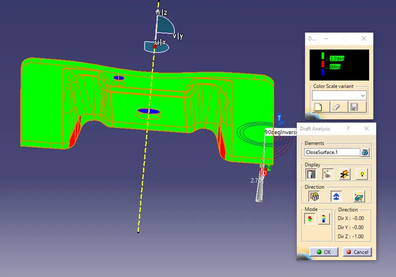
the draft angle of 2.7 degree is showing the negitive error
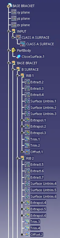
TREE STRUCTURE:
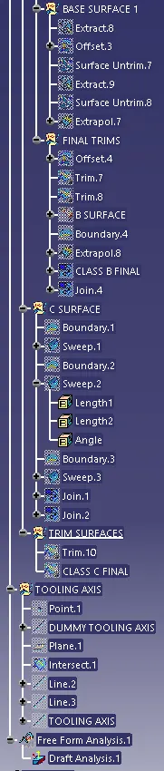
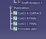
conclusoin:
THE SOLID MODEL OF THE BASE BRACET IS CREATED BY USING THE CLASS A AND DEVELOPED CLASS B AND CLASS C WITH THE THICKNESS OF 2.5 MAKING AN OFFSET OF THE CLASS A AND HENCE THE SOLID PART IS CREATED BY USING THE SURFACING COMMANDS AND PREFORMED DRAFT ANALYSIS FOR CLASS AND CLASS C .