Week 8 - Challenge 2 - Base Bracket Design
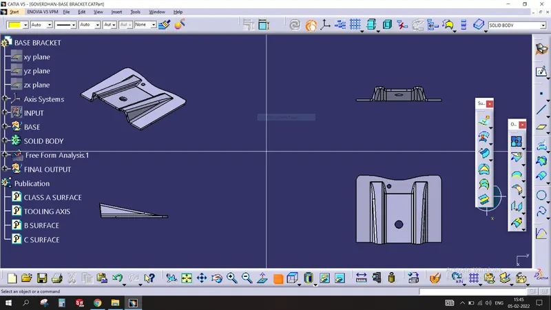
AIM: To create a Solid Base Bracket from the given Class A Surface as Input.
OBJECTIVE:The objective is to create BASE BRACKET using Class A Surface along with draft analysis and following the OEM Design standards.
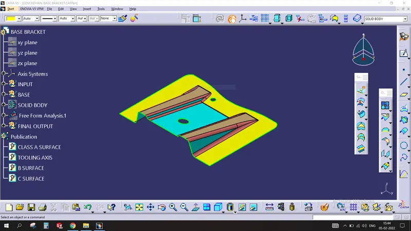
INPUT CLASS A SURFACE:
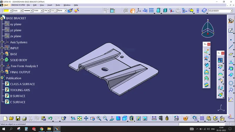
SOLID PART BODY:
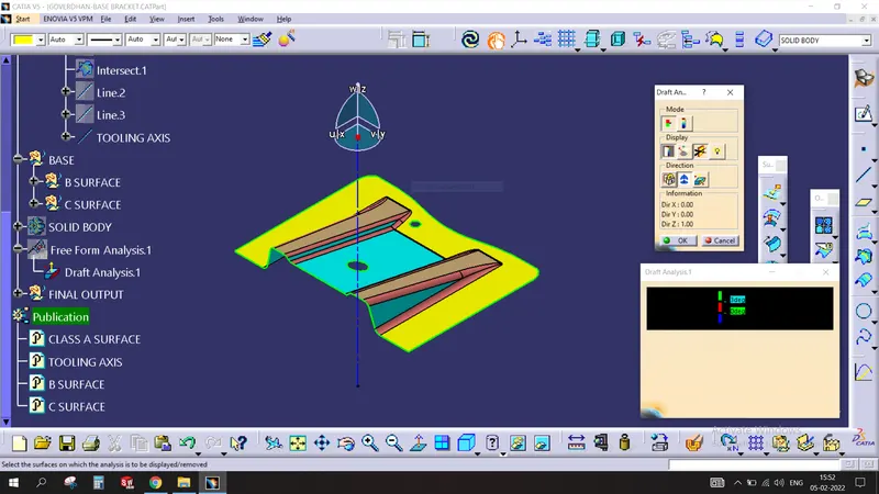
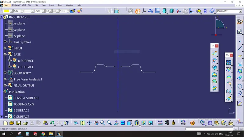
TOOLING AXIS CREATION:
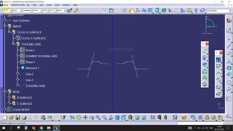
- Class A surface is first analyzed for creation of tooling axis which tells about the direction of the mould or core and cavity slides.The tooling axis plays a vital role in the plastic design as there should be clearance between the tooling axis and mould.
- The minimal of 3 degree draft angle is provided on the surfaces which are 90 degrees to avoid the Interference between the mould and Injection molding machine.
- The first step is to check wheather the given class A surface has continuity or not.
- The next step is to check the possibities of the tooling axis along x,y and z direction(NOTE : The surfaces must have clearance with the tooling axis and features such as holes must be cleared in the main tooling axis itself to avoid sidecore.)
- The Tooling clearance along x and Y are created and by using the bisecting line and tooling axis along x,y we will draw a TOOLING AXIS in which feature like Hole and the inclined surafaces don't interfer with tooling axis.
- The Tooling axis should be published along with changing the graphic properties of the Tooling axis for ease reconginization.
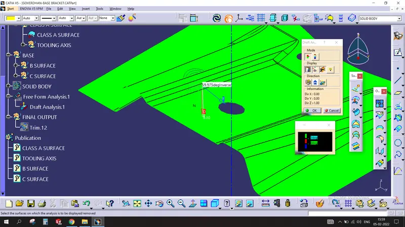
DRAFT ANALYSIS:
- Draft angle is nothing but the amount of the taper is provided on the core and cavity for ease ejection of the mould after cooling.
- After Injection moulding the plastic parts shrinks and get sticks to the core and it will make diffcultly in removal of the plastic part.
- If there is NO draft or taper is provide on the core and cavity the inner layers of the platic part will undergo wear and tear and there will NO smooth surface finish.
- The draft angle is provided on the both the inner and outer walls of the core and cavity.
- The Nominal draft angle is 3 degrees
- 5 degree draft can be given by the manufacturing cost will be more.
- The 7 degree draft is given for the textured surface.
STEPS FOLLOWED FOR THE DRAFT ANALYSIS:
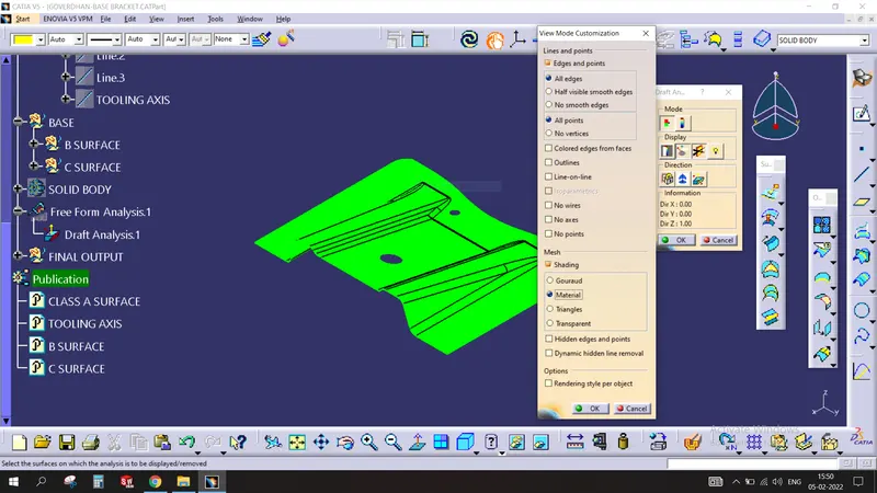
- The part created has to be changed to the material mode.
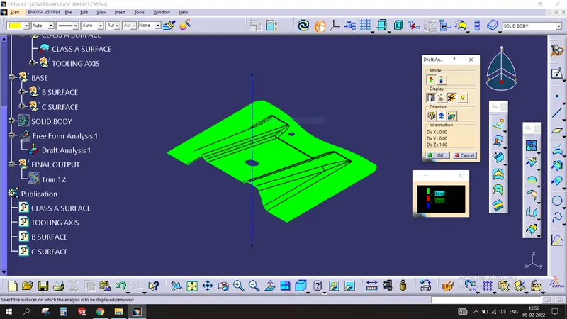
- compass is enabled and alligned to the tooling axis.
- Lock command is used to lock the position of the compass.
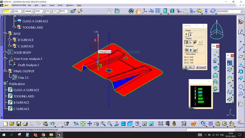
- color codes are classified and draft angle is analyzed.
- Running point analysis is used to display draft angle at a specific position.