Week 8 - Challenge 2 - Base Bracket Design
OBJECTIVE:
To create the base bracket component by the given class A surface and perform the draft analysis.
CLASS A SURFACE:
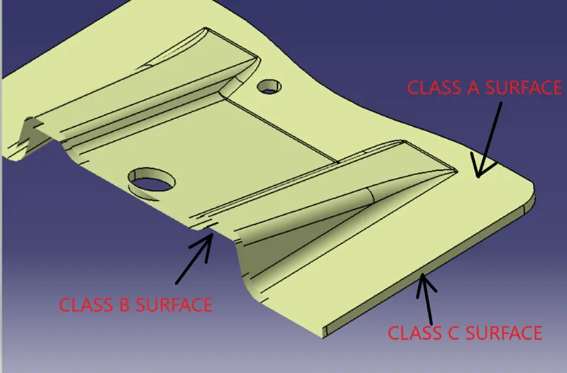
It is the outermost surface of the component with high accuracy and precision. It has aesthetic value and cannot be modified without authorization.
CLASS B SURFACE:
It is the inner surface of the component which we get after thickening it. The engineering features are attached to it.
CLASS C SURFACE:
It is the surface which joins the class A and class B surfaces along the boundaries.
BASE BRACKET DESIGN:
TOOLING AXIS CREATION:
Step 1: Check the boundary of the class A surface and ensure there is no gap in between the surface.
Step 2: Create a dummy tooling axis along Z direction.
Step 3: Create an intersect between the YZ plane and the class A surface.
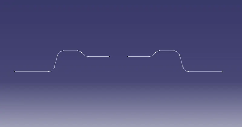
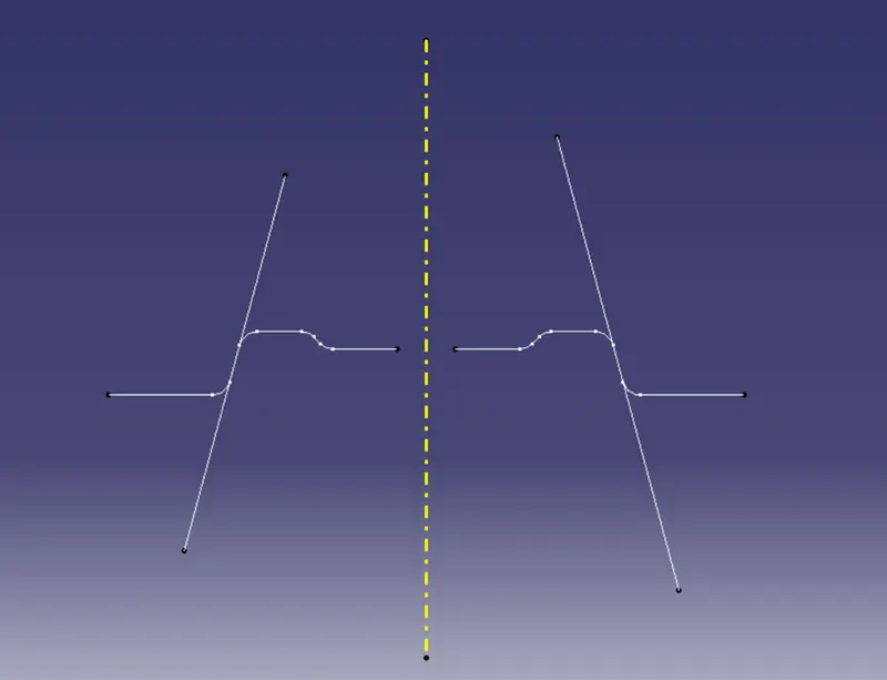
Step 4: Create reference lines with the intersect produced that are almost parallel to the dummy tooling axis. We can ignore the lines that are perpendicular to the axis.
Step 5: Create a bisecting line for the reference lines created and this line indicates the final tooling axis.
DRAFT ANALYSIS:
Step 1: Change the view to customized view and enable the material in shading option.
Step 2: Insert the feature draft analysis.
Step 3: Click the compass icon and place the compass along the tooling direction.
Step 4: Lock the draft direction and select the component to draft.
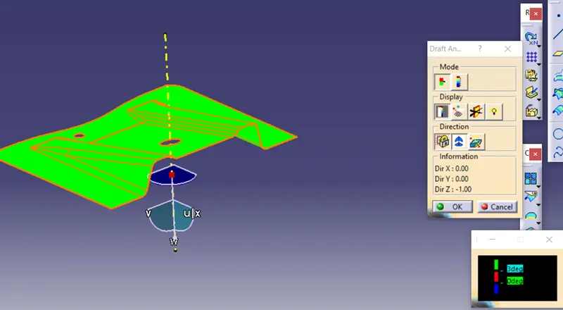
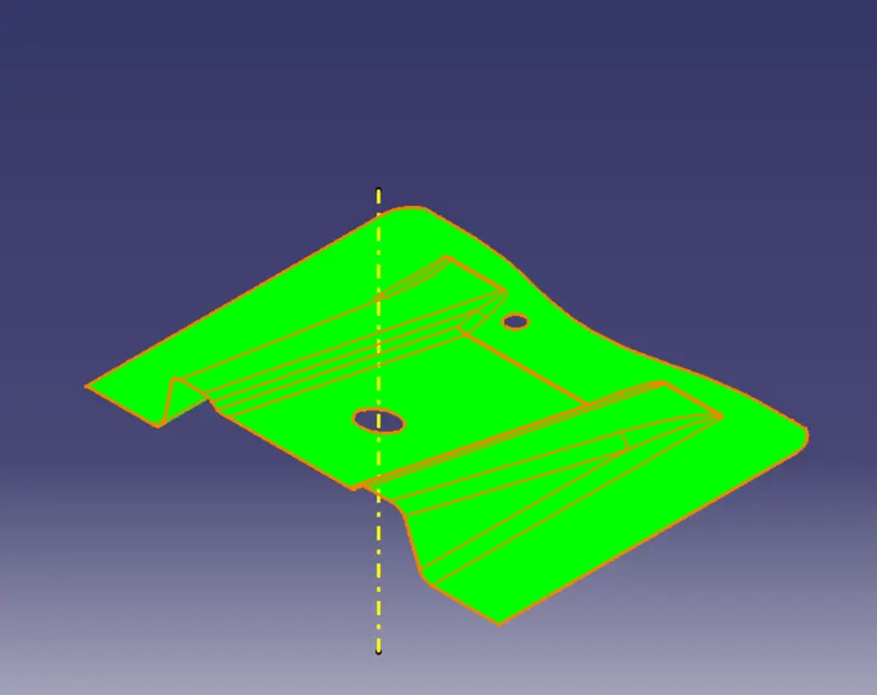
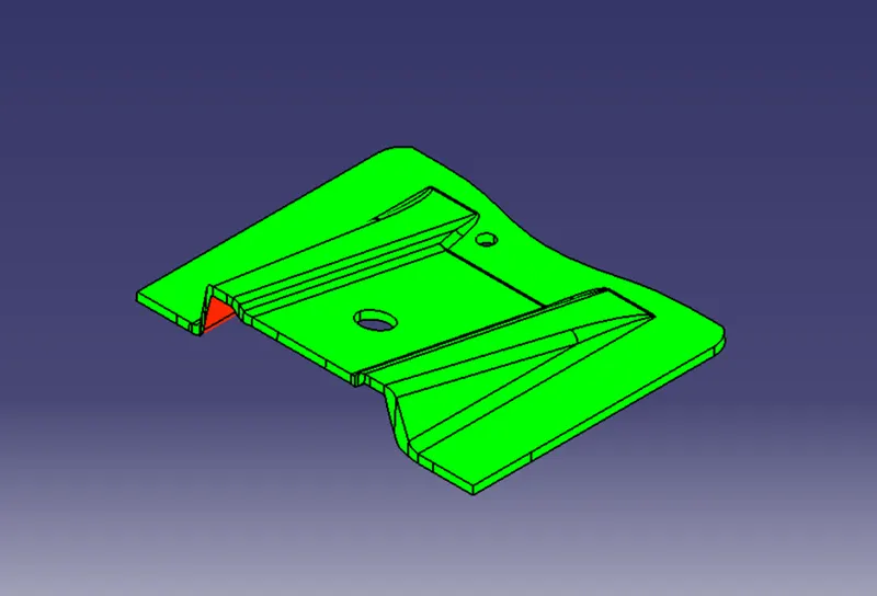
Step 5: Enable the color scale and change the draft value as required. Here 3 degree is given as draft angle.
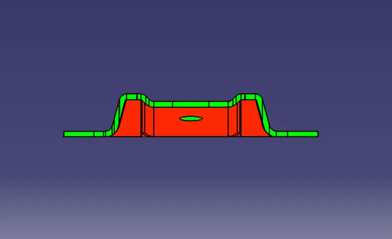
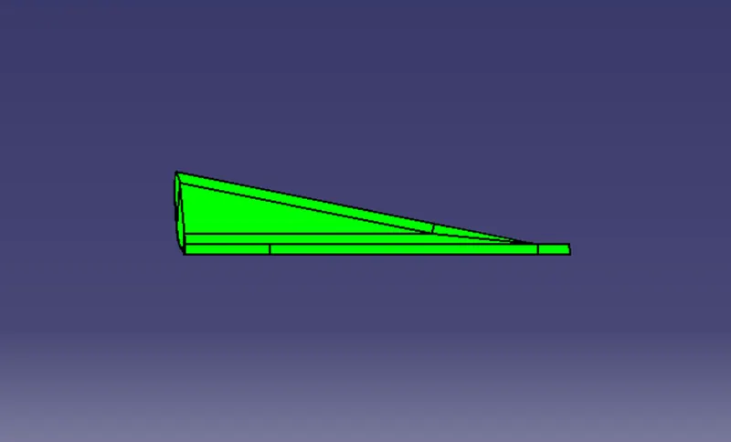
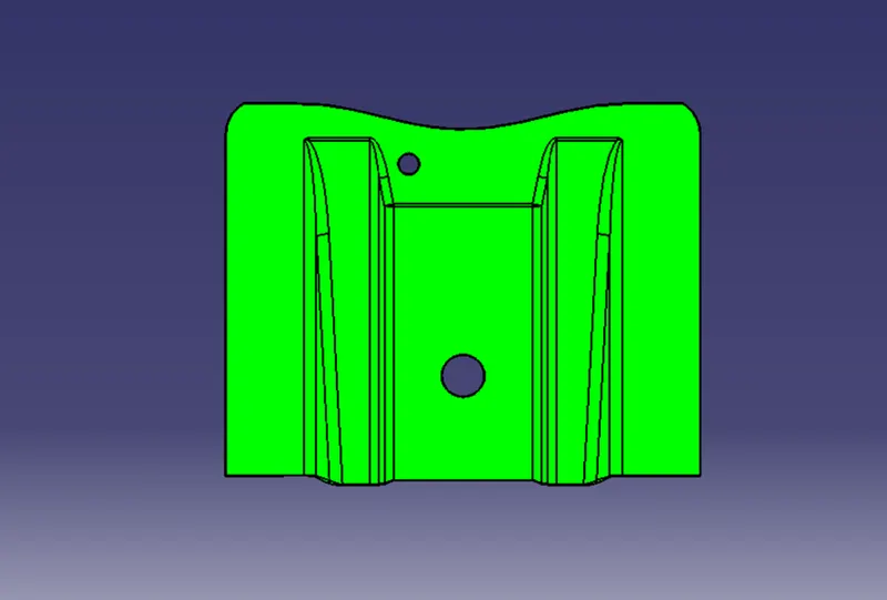
Step 6: The green color indicates that the surface is more than 3 degree from the tooling direction. The blue color indicates that the surface is 0 to 3 degree from tooling direction. Red color indicates that the surface is less than 0 degree from tooling direction which indicates the negative draft.
CLASS B SURFACE:
Step 1: Extract the individual surfaces from the class A surface.
Step 2: Untrim the extracted surfaces and extrapolate them as required.
Step 3: Offset the extrapolated surfaces inwards to get the thickness (2.5mm) of the component.
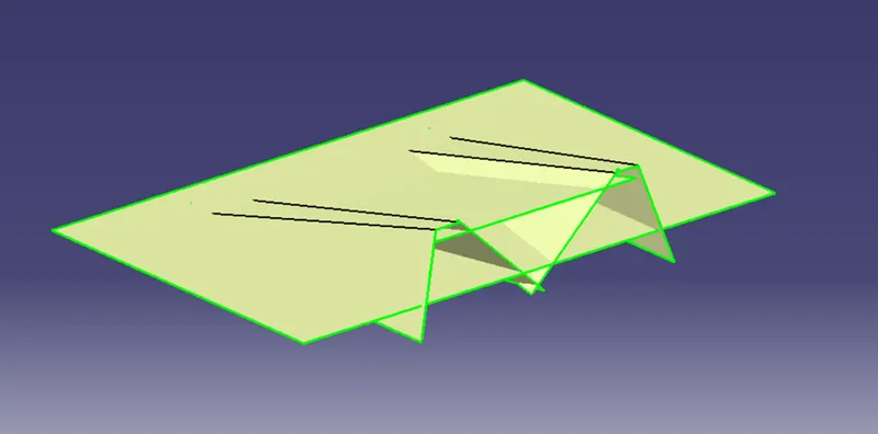
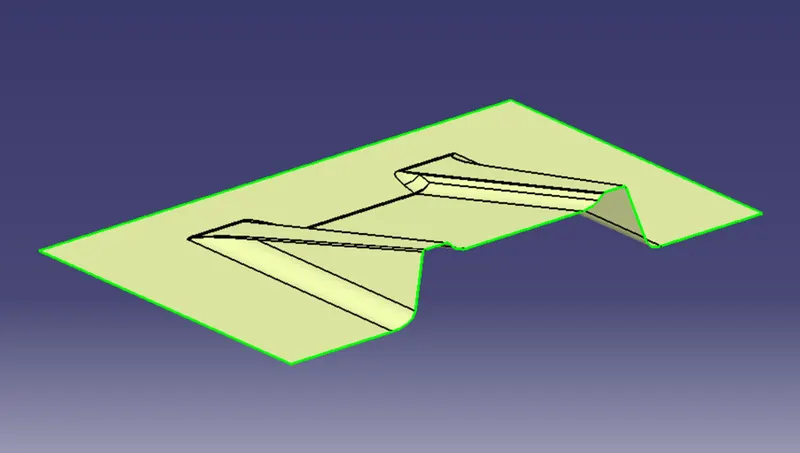
Step 4: Trim the offset surfaces and give fillets as required to get the class B surface.
CLASS C SURFACE:
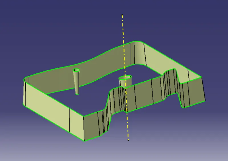
Step 1: Create the boundaries for the class A surface.
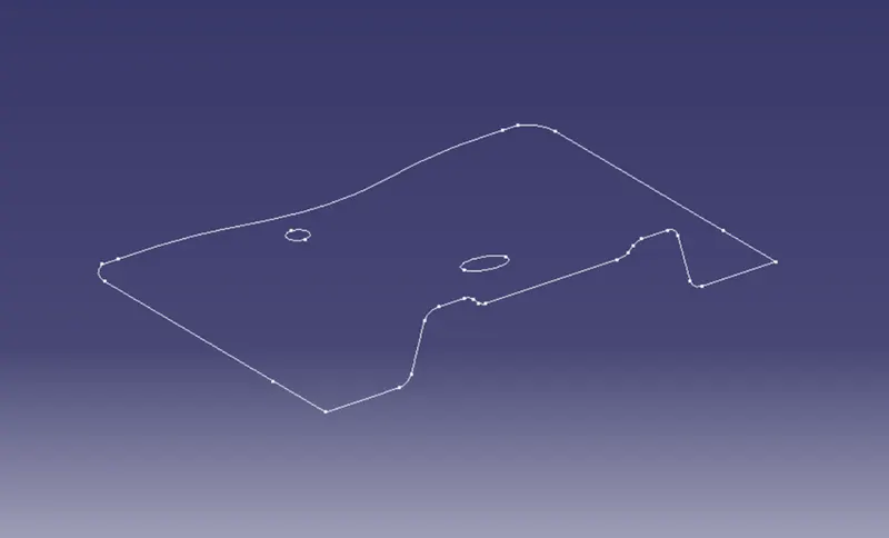
Step 2: Sweep the boundaries along the tooling direction with required draft angle to get the class C surface.
FINAL TRIM:
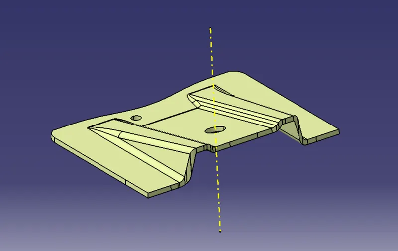
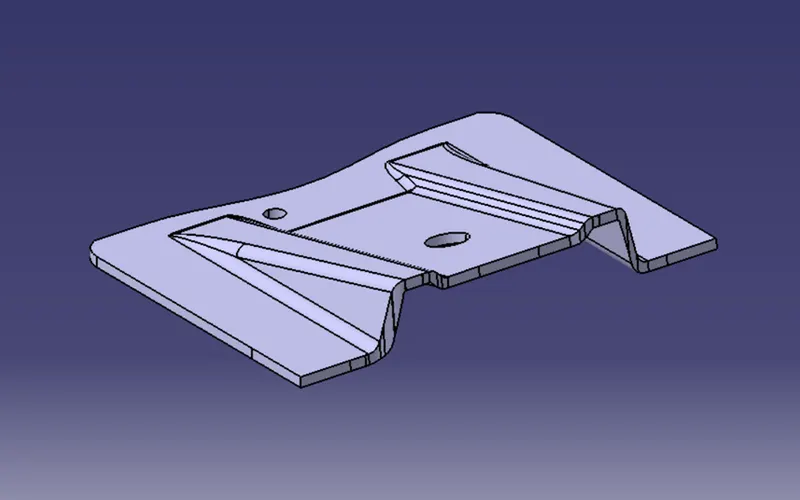
Finally trim class A, class B and class C surfaces to get the base bracket surface and use closed surface feature to create a solid component. Then perform draft analysis by following the above steps.
DRAFT ANALYSIS ON DIFFERENT VIEWS:
ISOMETRIC VIEW:
FRONT VIEW:
SIDE VIEW:
TOP VIEW:
CONCLUSION:
Thus the base bracket is created with the given class A surface and draft analysis is performed on it.