Week 8 - Challenge 2 - Base Bracket Design
Challenge 2 - Base Bracket Design:
OBJECTIVE:
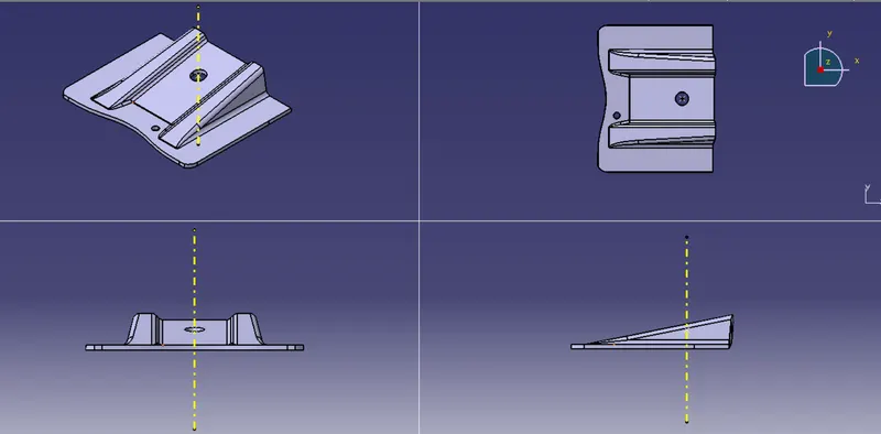
Create the Base Bracket Plastic component through the given Class-A surface. To begin with, the tooling axis for the given Class-A Surface should be created meeting the requirements of the draft angle and at the end perform the Draft analysis on the model.
TOOL:
Catia v5

INPUT:
We've got a class A surface from class A team as a input
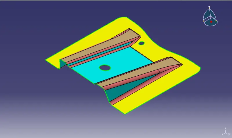
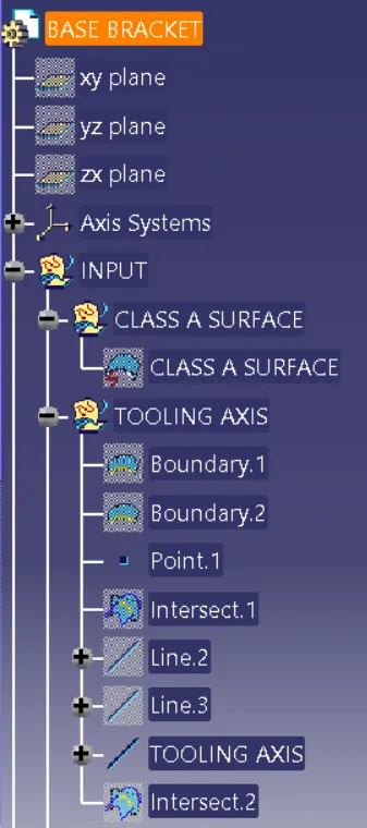
So, before we jump into the design procedure we'll have to have a tooling axis so let's have a look at how'd got that
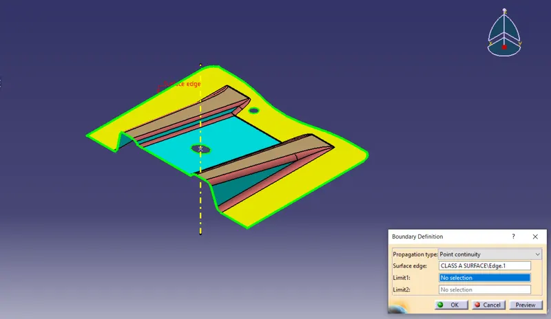
First i took a boundry of class -A surface
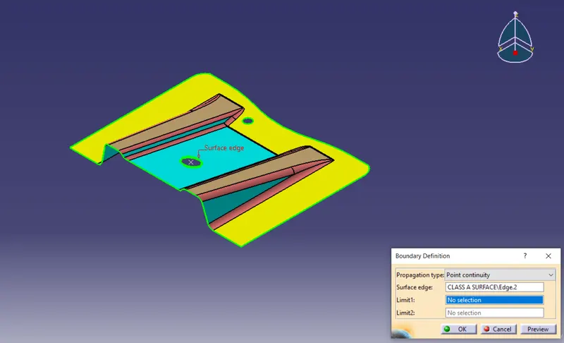
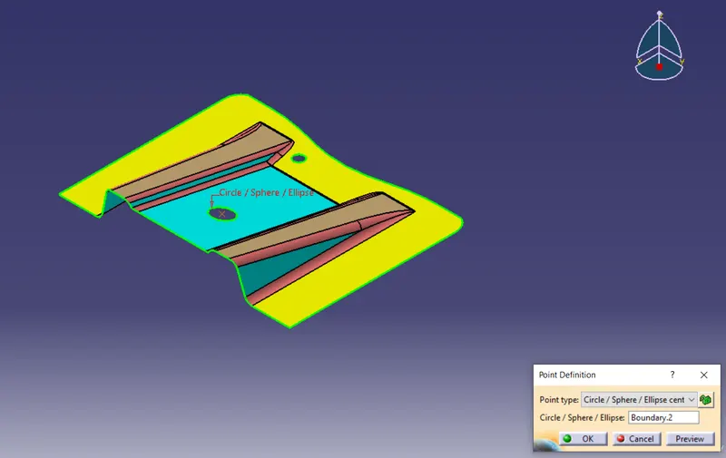
then i took a boundry of the circle in a bigger diameter as i considerd it where am i gonna create the tooling axis
then i created the point over the circle
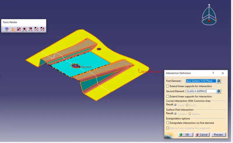
then i created the intersection line along with x direction
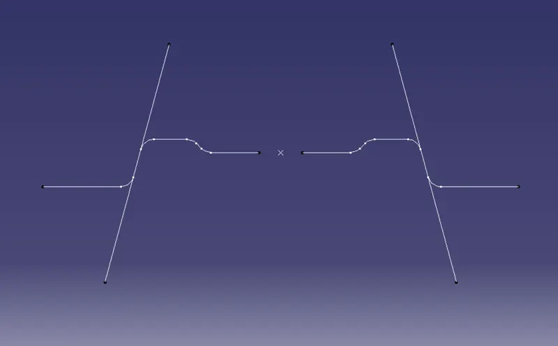
then i created the refference lines at the both side of my intersection line which i took along with x direction
And i created the line between the refference line by bisecting method
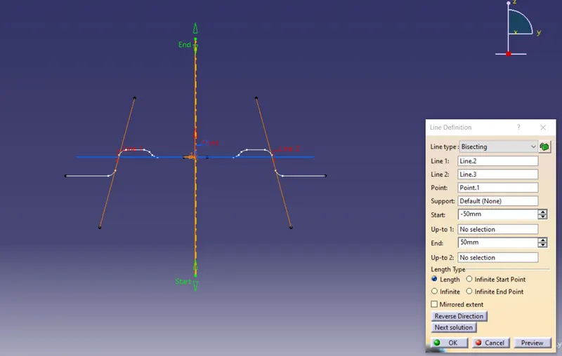
And eventually we've got a proper tooling direction
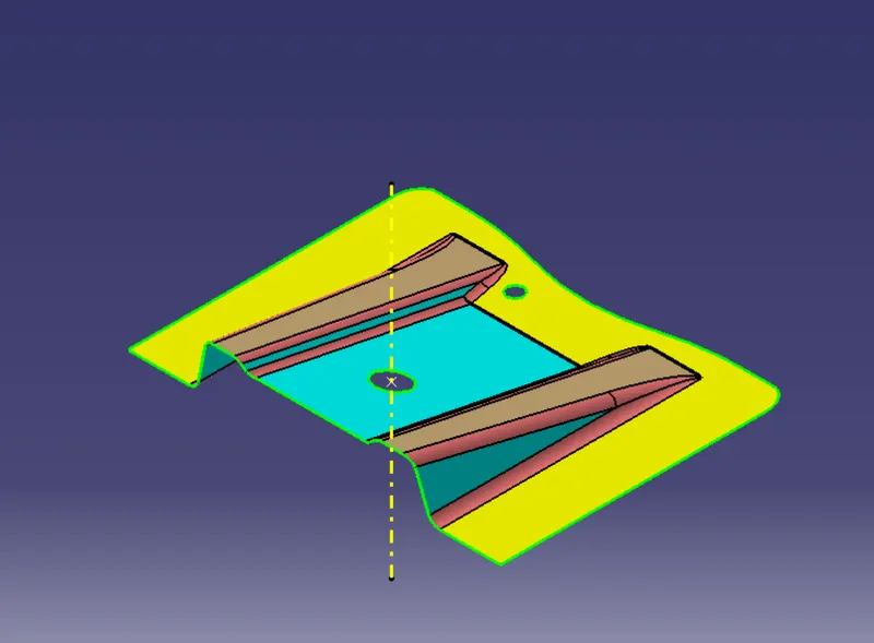
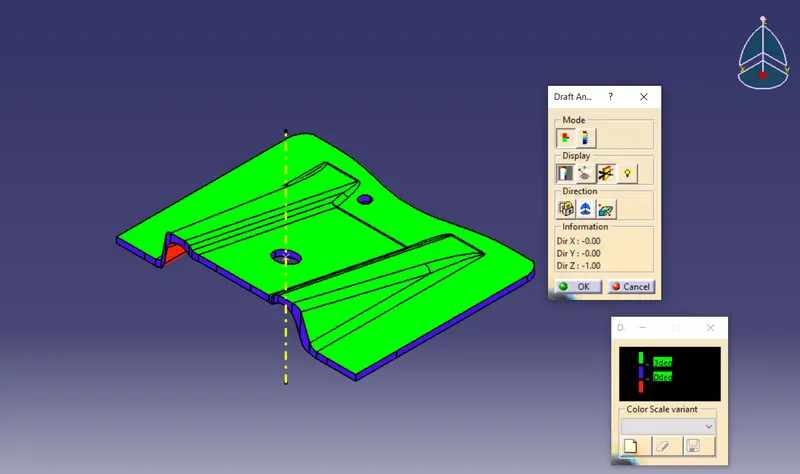
Then i'd perform the draft analysis over the class-A surface since there's no negative draft we can go further
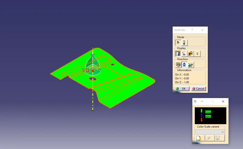
DESIGN PROCEDURE: There's a first thing in this case is to create the class-B surface so, let's have a look at how do we approach with class-B surface
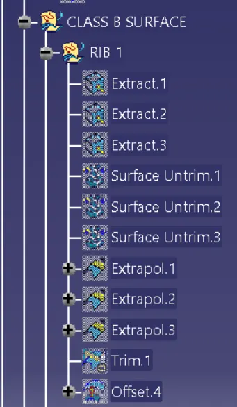
After i've got a class A surface i've extracted the surfaces on the side ribs.
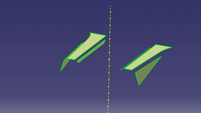
then untrim them all and extrapolated that surfaces
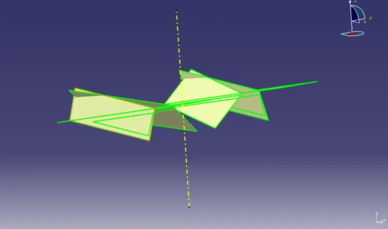
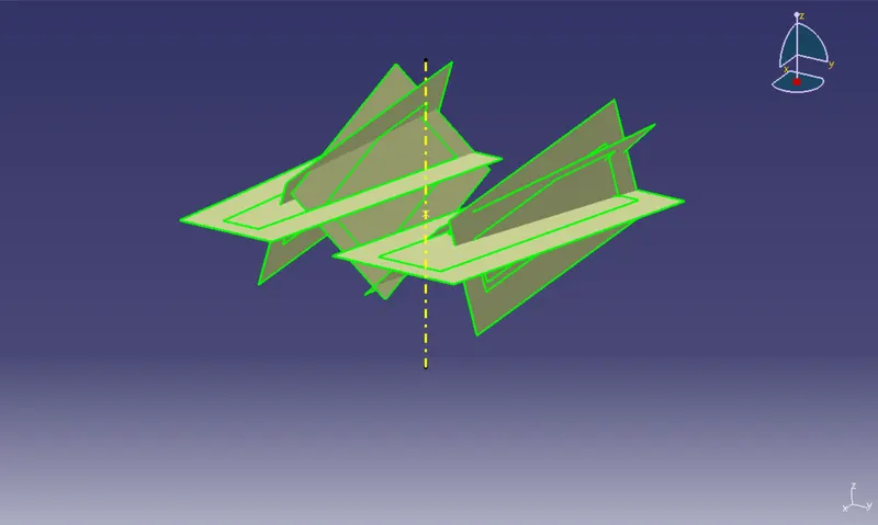
Then i trimmed off the unwanted surfaces
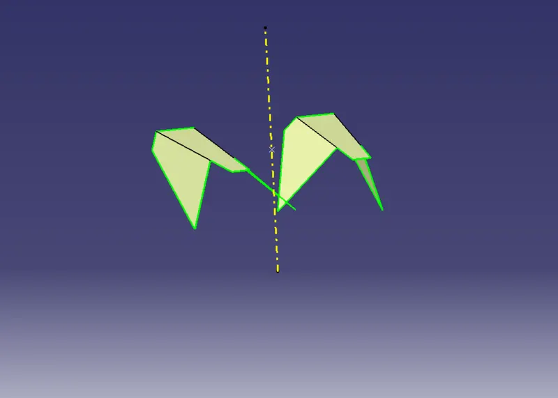
then offseted them all around 2.5mm since it's required thickness
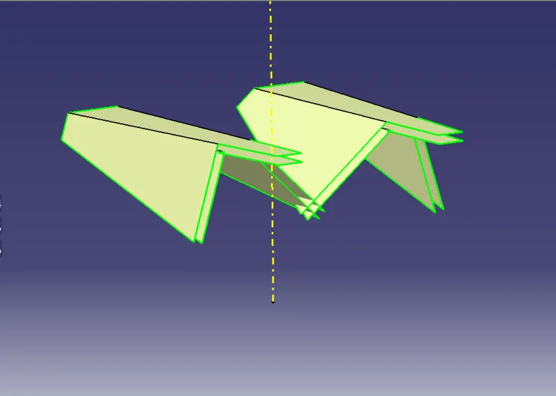
After all that i extracted the base surface which is between the ribs
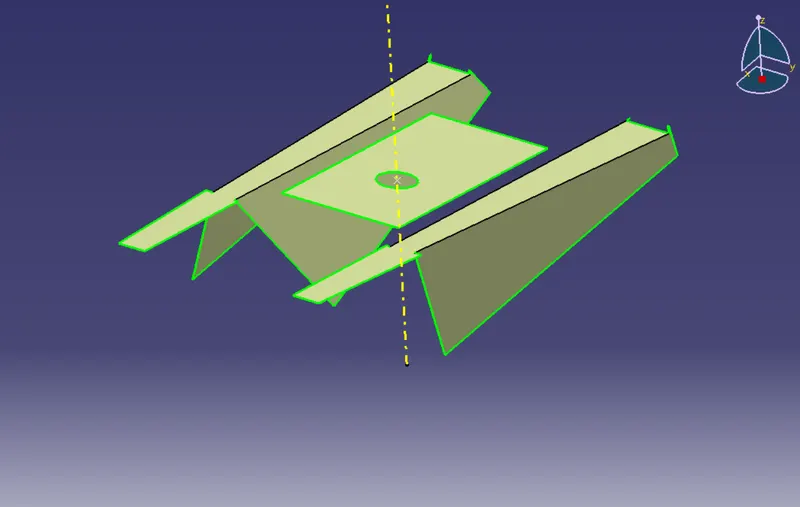
then untrimmed it
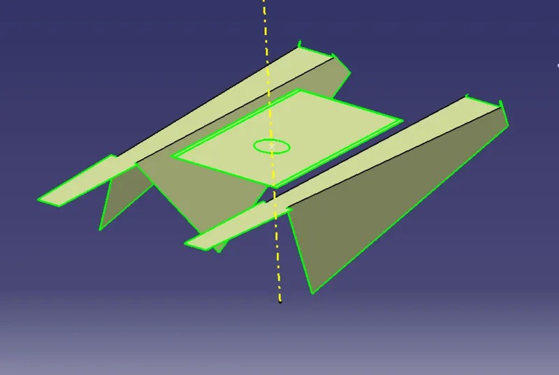
And as before i've extrapolated
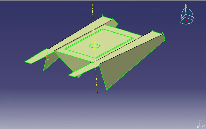
then offseted the surface around 2.5 mm
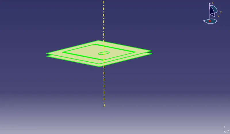
After i done with ribs and base surface i begin with creating the mounting base
Here also i done with whatever methods i followed on previous surfaces so, i extracted the surface which am i highlighting in orenge color
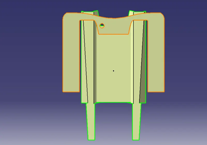
then i untrimed it
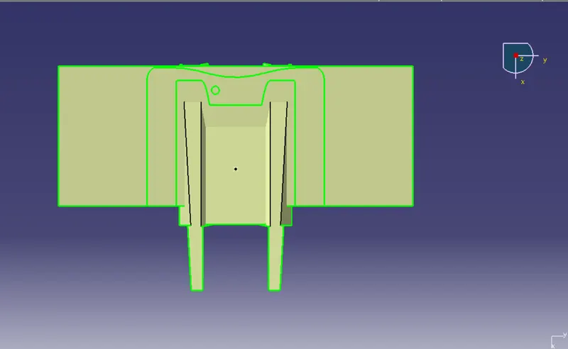
then again extrapolated that surface
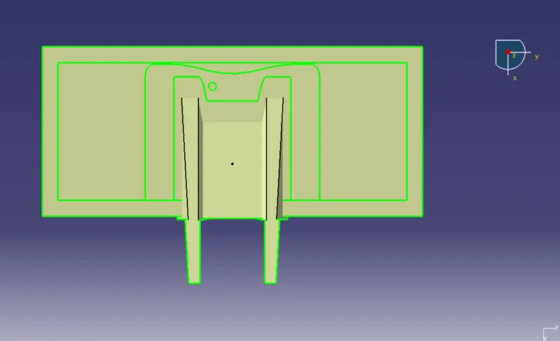
then i offseted that surface around 2.5mm
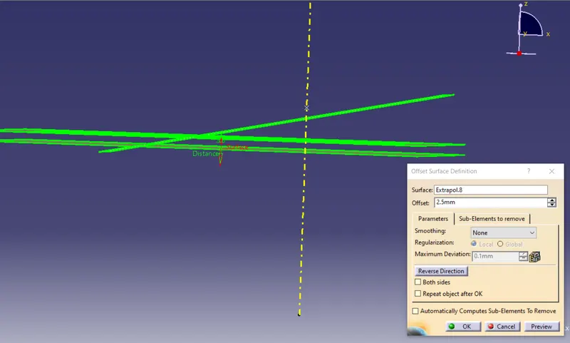
then we got the surface which is ready to get trimmed
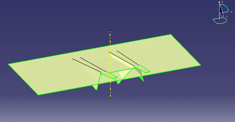
At the beginning i trimmed the base surface with ribs
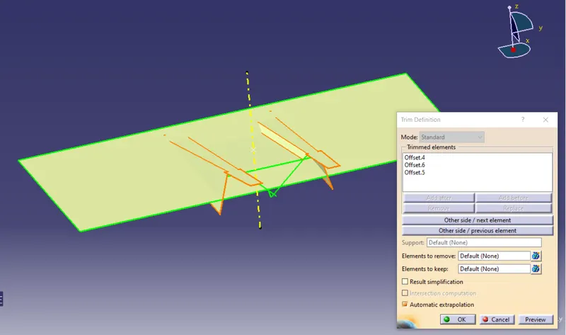
then i trimmed the mounting base with the ribs

And after filleted all the edges with radius 5.5mm we've got our final output class-B surface
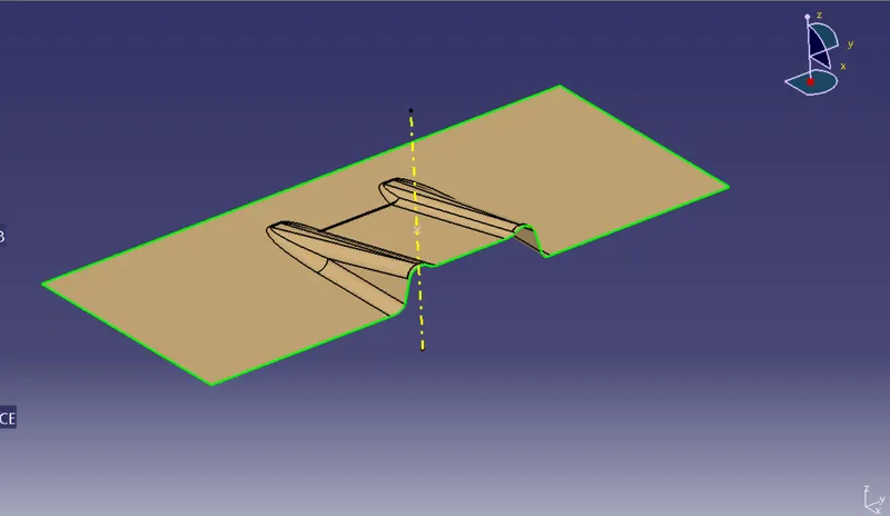
Sofar, we've done till creating class - B surface
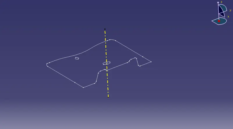
First of all i took a bountry from class-A surface
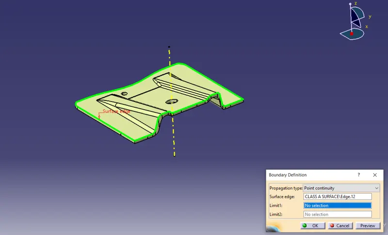
then i took a boundry of the holes as well
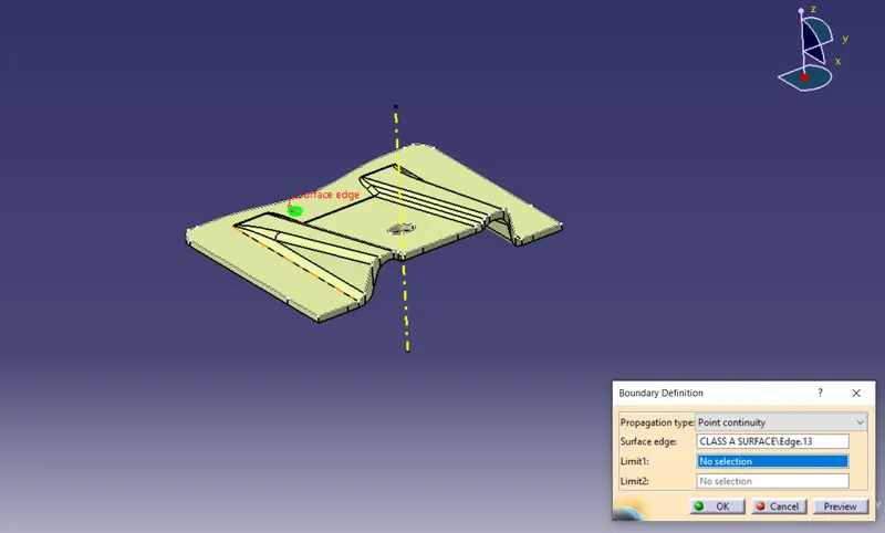
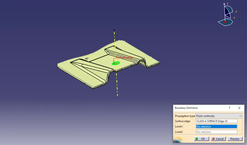
So, now we've got all the boundrys
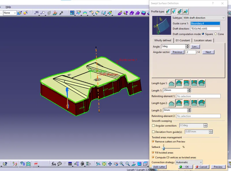
And i created my first sweep with boundry 4
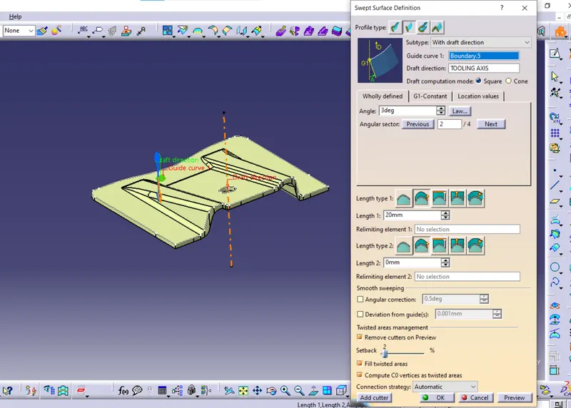
And i created sweep for the holes which are on the top of the class -c
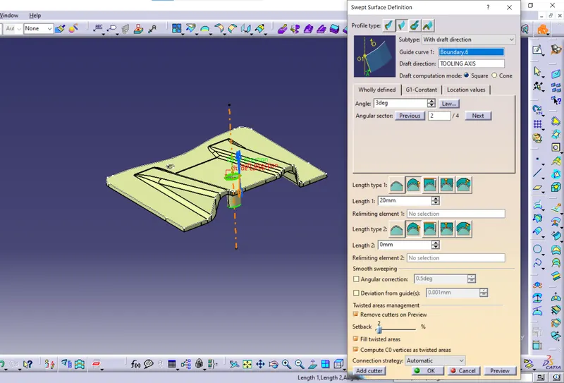
And i first joined the class a and sweep 1 (class-c)
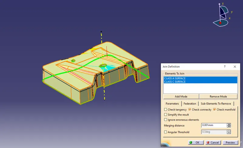
Then i joined the sweeps of the holes with class-A
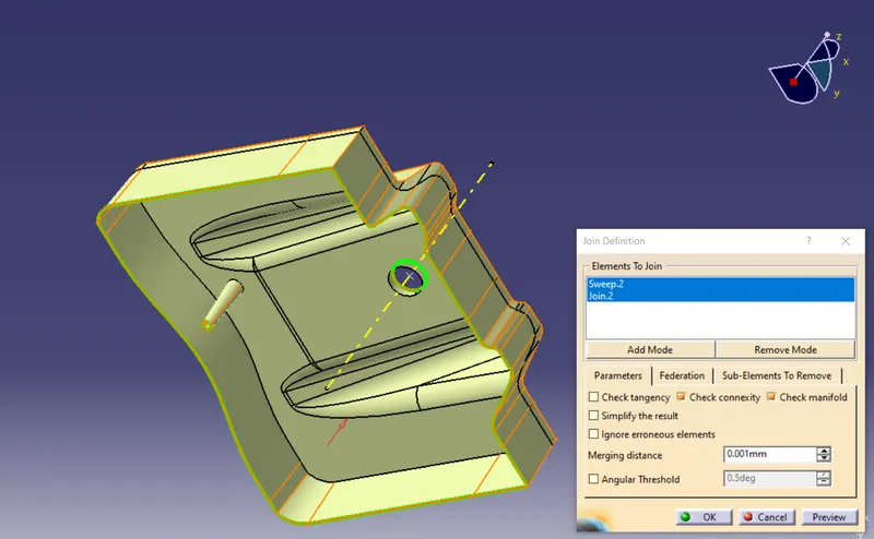
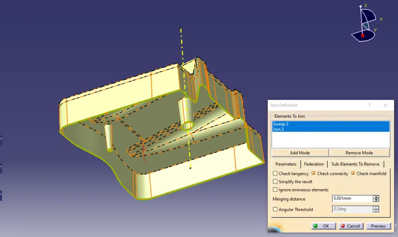
then i trimmed of class-B surface with join which i created with class-A and C surfaces
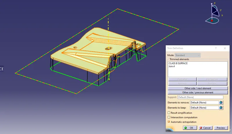
And now we've got the required surface which's gonna get solidified
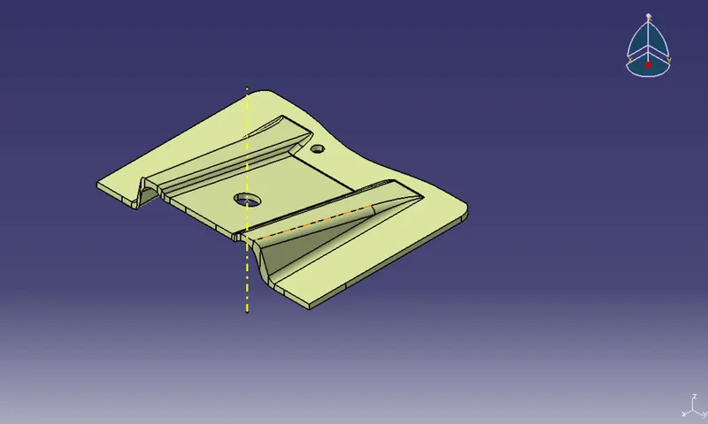
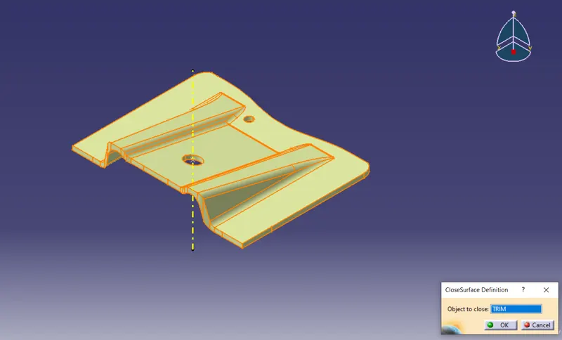
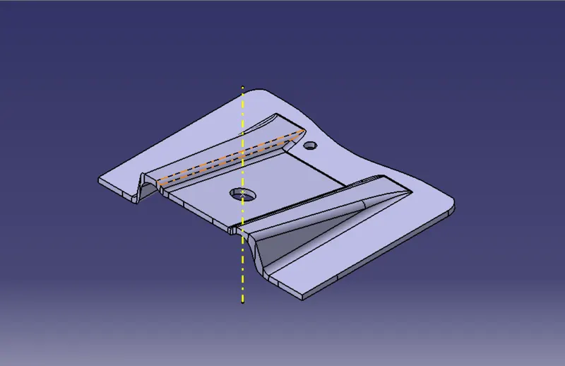
After that i've made the soild component by close surface tool
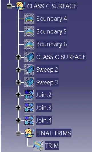
Tree structure of geometrical set:
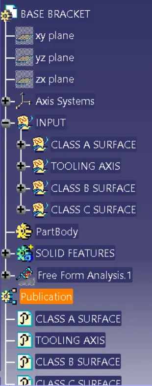
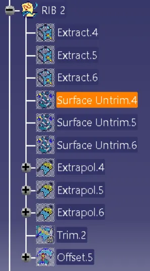
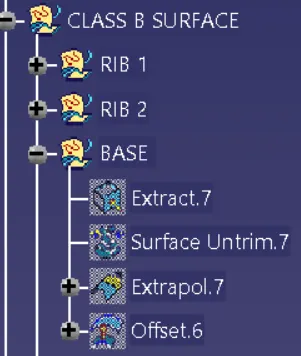
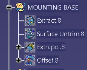
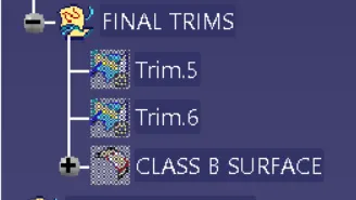
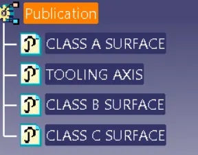
There're some feautures which needed to be bublished:
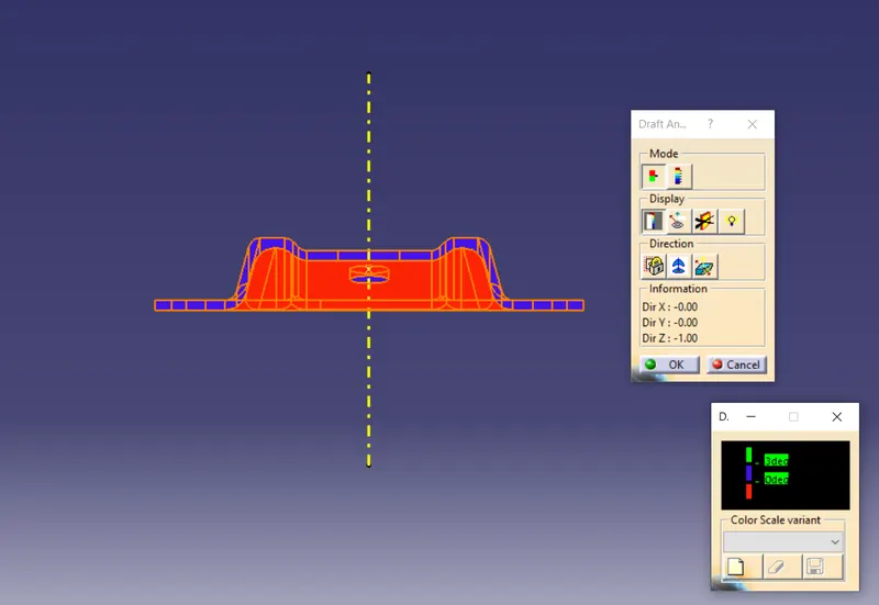
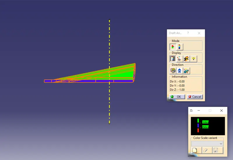
Report of the draft analysis on the soild part:
FRONT VIEW:
LEFT VIEW:
RIGHT VIEW:
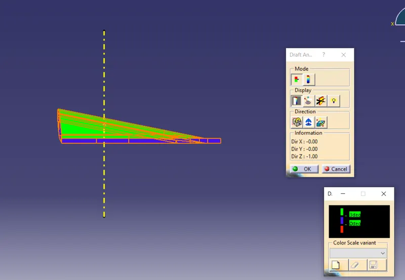
TOP VIEW:
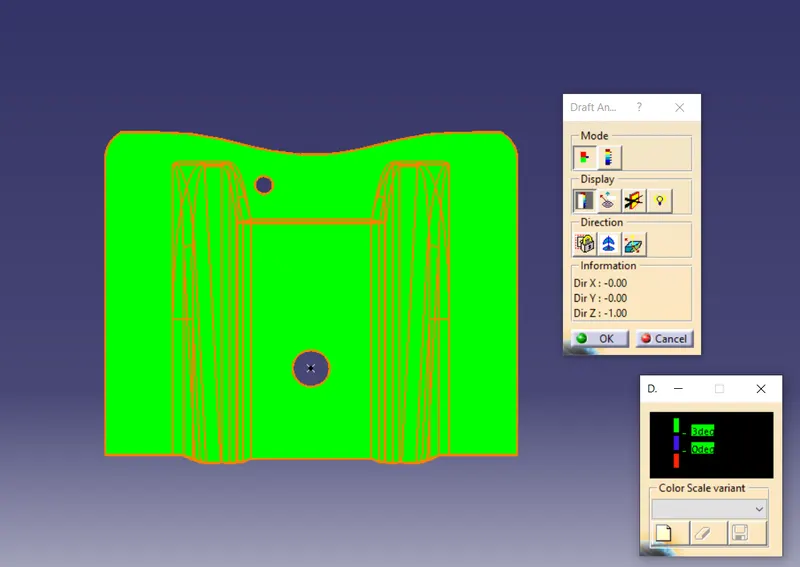
ISO-METRIC VIEW: