Week 8 - Challenge 2 - Base Bracket Design
BASE BRACKET DESIGN
OBJECTIVE:
To create a B and C surface for the given input and a tooling axis for the respective model.
B SURFACE:
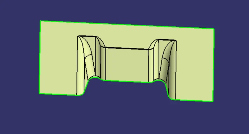
The B surface has all the engineering features in it whereas the class A is an aesthetic surface where no modifications should be done.
C SURFACE:
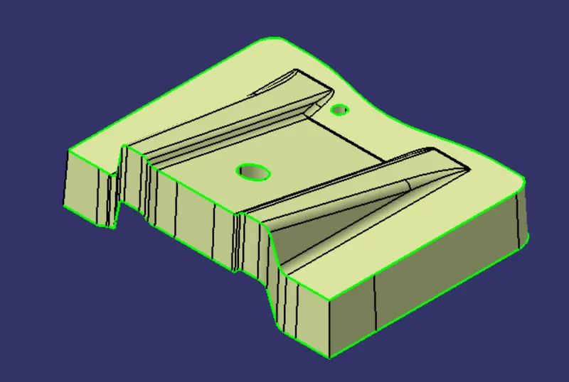
The C surface is the one which joins the class A and class B surface.
GIVEN INPUT:
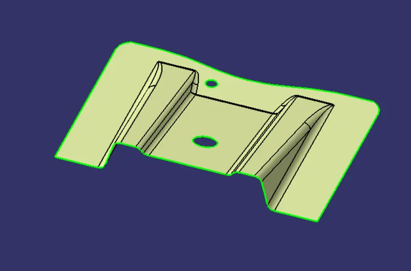
TOOLING AXIS:
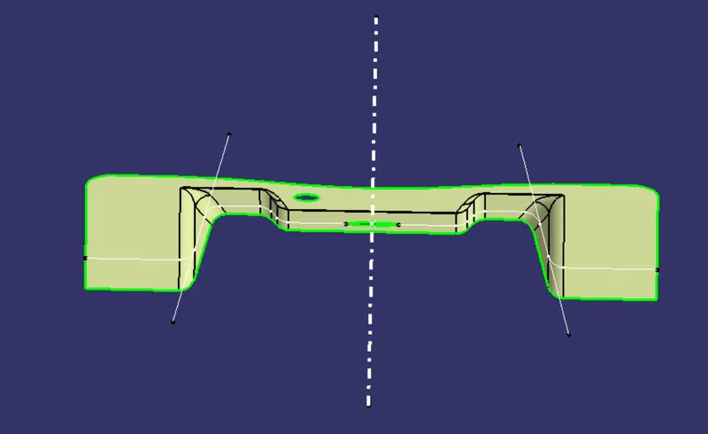
Here in this particular model the tooling direction in X&Y is not feasible as it has holes on the top of the surface from the respective views.
The only possible tooling direction which can clear the hole is the Z direction.
Now tooling direction is created by bisecting method using the two side reference lines.
DRAFT ANALYSIS:
A min of 3 degree draft is required on all the faces of the surface to clear the draft analysis.
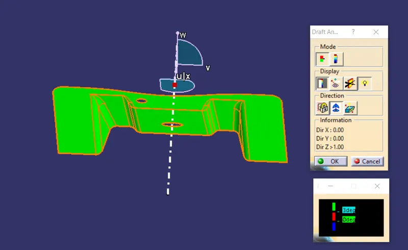
Here the colour green infers that all the faces of the surface has more than 3 degree draft.
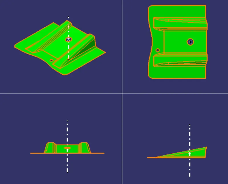
VARIOUS ORIENTATION OF THE DRAFT TEST:
CREATION OF B SURFACE:
After done with the tooling axis,using the commands such as extract,untrim,extrapolate offset and trim a B surface is created using the class A.
C SURFACE:
Using the sweep command and with the reference of tooling direction the joining surface is created.
FINISHED SURFACE:
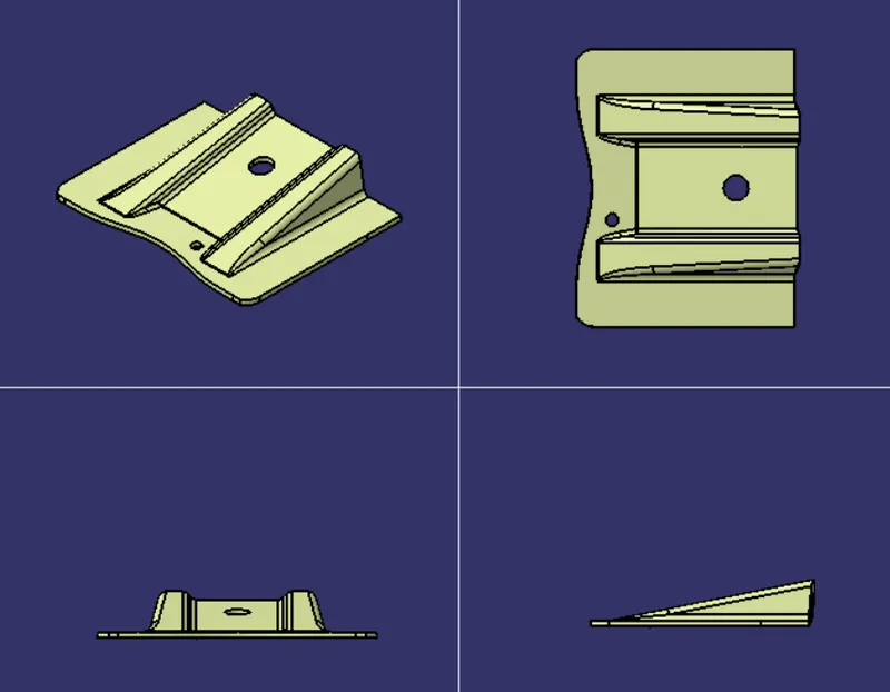
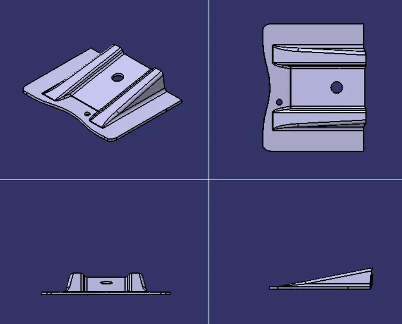
Now using the trim option the class A,B&C are joined together as a single part and converted into a solid
Different views of the Base Bracket:
TREE STRUCTURE:
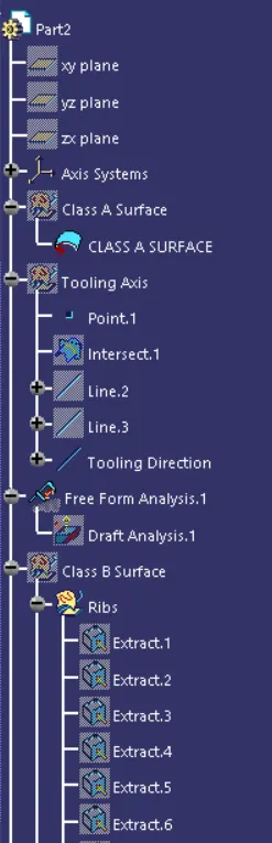
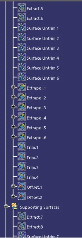
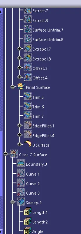
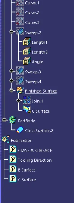
CONCLUSION:
To conclude the given base bracket is designed with class B&C surface and a respective tooling direction is created for the model.