Week 8 - Challenge 2 - Base Bracket Design
Challenge - Base Bracket Design
Objectives: Create the Base Bracket Plastic component through the given Class-A surface. To begin with, the tooling axis for the given Class-A Surface should be created CLASS B & CLASS C SURFACES and to make a solid body from the surface
CLASS A SURFACE
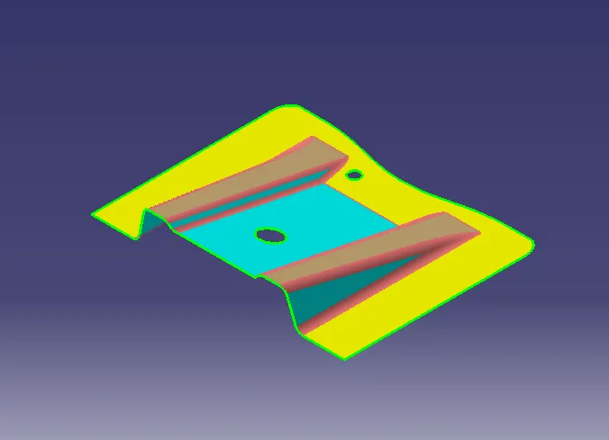
Tooling axis on a base bracket
Input the class A surface of base bracket model in CATIA
first, create the point(reference point) on the center point of a circle (hole)and create a dummy tooling direction in the Z direction
create a plane on a point in the YZ plane and intersect with the plane
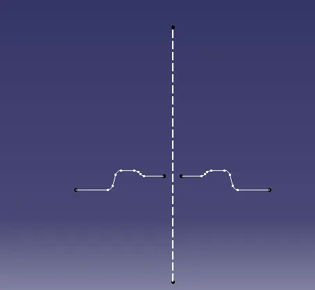
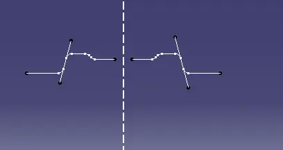
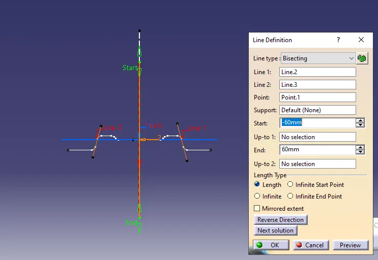
Draw two lines as shown in the below fig and These lines help to bisect the midline and create a real TOOLING AXIS
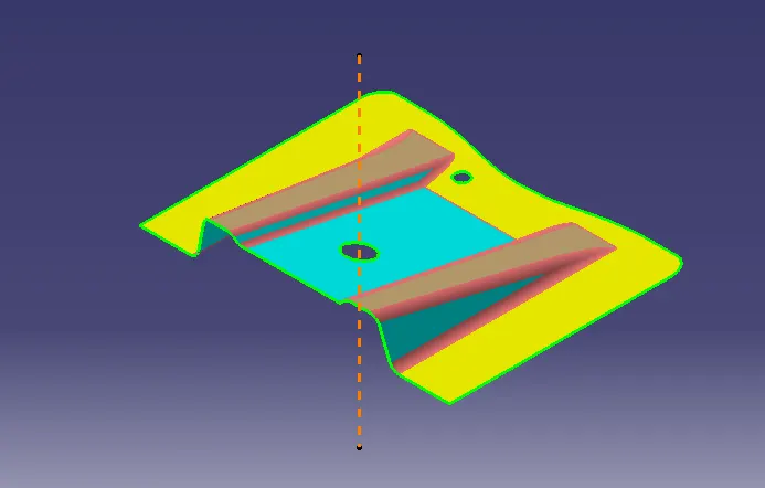
CLASS B SURFACE
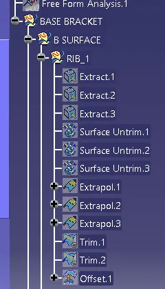
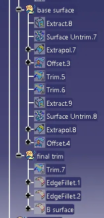
For creating a Class B surface extract the class A surface of Ribs & base(individual surfaces) consider offsetting the thickness of the component as2.5mm. offsetting the extracted surfaces and UNTRIM the Extracted offset surface using the UNTRIM tool. Extrapolate the untrim surface for trimming the Ribs and Base surface. The final output of Class b surface as shown in below fig
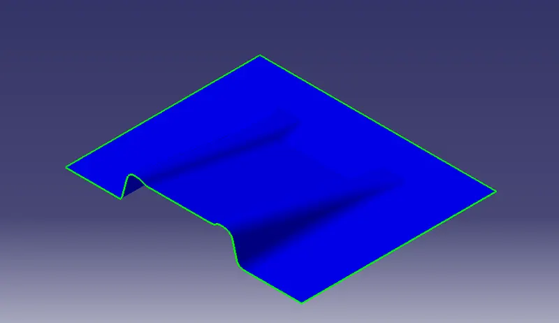
CLASS C SURFACE
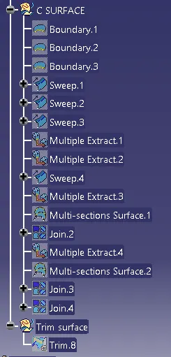
To create a Class C surface, extract the Boundaries of a Class A surface as shown in figure
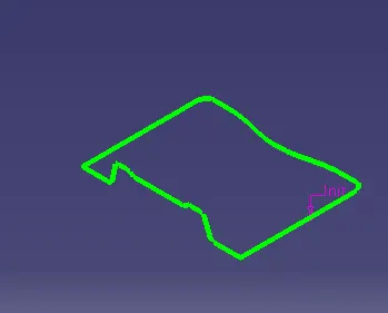
Create the surface using the sweep tool
For the sweep, tool Go to the tool bar>sweep>profile type> line >subtype>with draft direction select the guide curve(Extract boundaries)
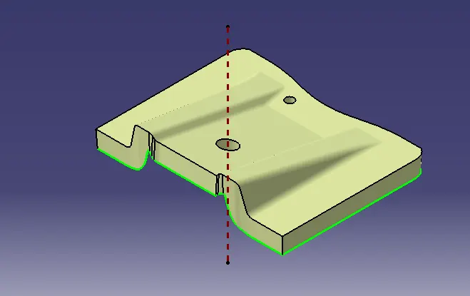
CROSS-SECTIONAL VIEW OF CLASS B&C SURFACES
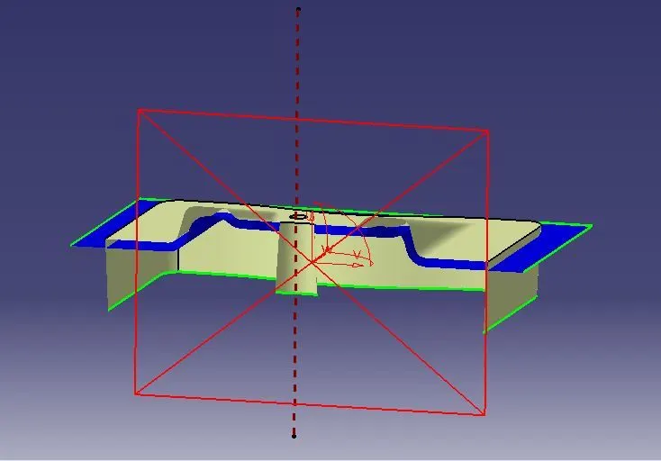
TRIM SURFACE OF CLASS B & C SURFACES
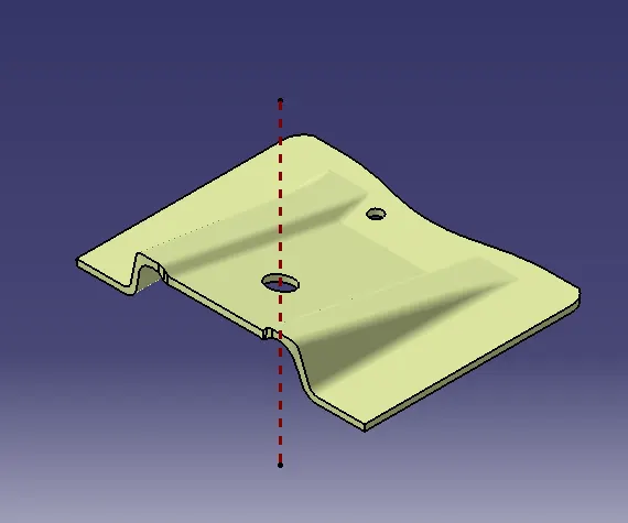
SOLID PART BODY OF BASE BRACKET
Finally using Close surface tool form part workbench for converting surface body to solid body
ISOMETRIC VIEW
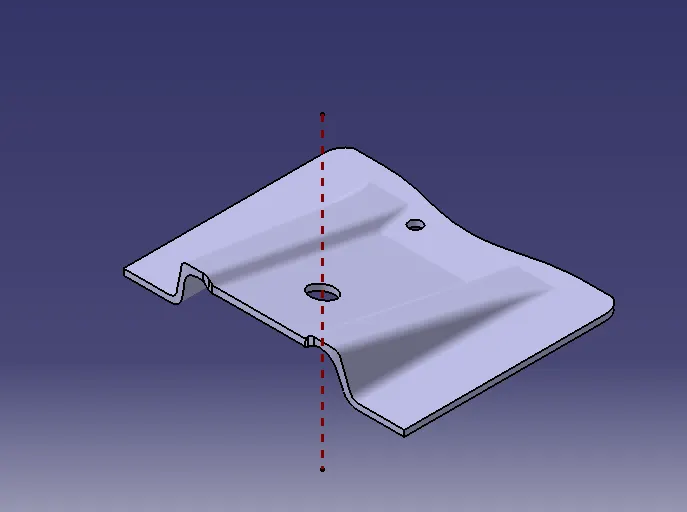
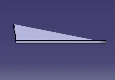
FRONT VIEW
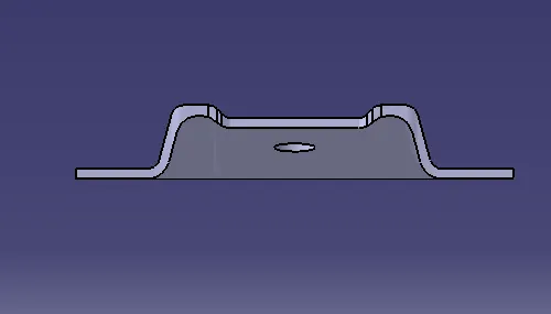
RIGHT SIDE VIEW OF THE BASE BRACKET
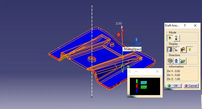
Draft analysis
TREE IMAGES OF CLASS B SURFACE
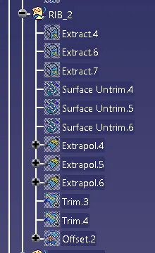
TREE IMAGES OF CLASS C SURFACE
TREE IMAGE OF PART BODY

Conclusion: Hence successfully created CLASS B&C surfaces and successful design a solid part body from surface body