Photo Realistic Rendering
American Chopper
Objectives:
Create American chopper parts by using solid modeling, assembly of an American chopper, rendering of an American chopper
INTRODUCTION OF SOLID WORKS:
Solid works main idea for users to create drawing directly in 3D or solid form. From this solid users can assemble it directly on their workstation checking clashes and functionality of it. Creating a drawing is easy just drag and drop the solid into the drawing block
Introduction of an American chopper:
American chopper started in 2003 and was one of the most popular motorcycling shows. It focuses on Paul Teutul Sr, his son Paul Teutul Jr, and their company, Orange County Choppers. It is located in Orange County, New York, and was founded in 1999. They focus on restorations and customizations of choppers built in the US.
Design methodology:
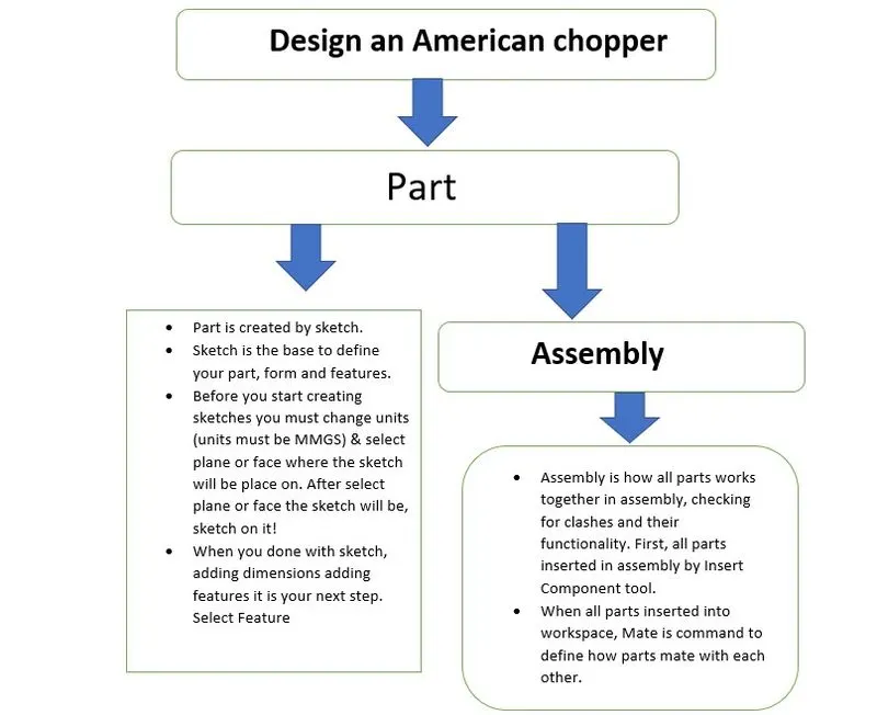
Description:
Command used:
- Sketch
Line: sketches a line. Click place to the point, drag, and release when the point
Spline: sketches a spline. Click and drag to create each spline segment double click to complete the spline
Circle: sketches a circle. Click to place the center of the circle then drag and release to define its radius
Rectangle: sketches a rectangle at an angle.3 point rectangle at an angle
Use three clicks to define the rectangle by placing three adjacent corners
Arc: sketches a 3-point arc. Use two clicks to place start and point then use a third click to specify the radius or to reverse the arc
Ellipse: sketches to complete ellipse. click to place the then use two or more click to define the axis of the ellipse
Straight slot: sketches a straight slot. use three clicks to place the starting point define the length and then define the width of the slot
Smart dimensions: create a dimension of one or more selected 2D and 3D sketch entities.
- Extrude boss\base: extrude a sketch or selected contours in one or two directions to create a solid feature. Use the extrude property manager to control where to extrude starts from, and the property manager or instant drag handle to define its direction and extent
- Revolve boss\base: revolves a sketch or selected contours an around axis to create a solid future. Use the revolve property to define the axis of revolution, and the property manager or instant drag handle to define its direction and extent of the revolving
- Extrude cut: cut a solid model by extruding a sketched profile in one or two directions. If the cut affects multiple bodies in multiple body parts, you can select which bodies to keep the dialog box
- Revolve cut: cut a solid model by revolving a sketched profile around an axis. If the cut affects multiple bodies in multiple body parts, you can select which bodies to keep the dialog box
- Liner pattern\circular pattern: pattern features, faces, and bodies in one or two directions. You can select the reference geometry to define the pattern. You can also skip the instance.
- Swept boss\base: sweeps a closed profile along an open or closed path to create a solid feature. You can use options in the profile manager such as guide curves, profile orientation options, and twist to create a wide variety of shapes
- Fillets\chamfer: creates a rounded internal and external face along one or two edges on a sold or a solid feature. Fillets can be of constant or variable size. Use the fillet property manage to select the fillet type and then set other options appropriate to the type
- Mirror: mirror features, faces, and bodies about a plane or a planer's face. in assembly, you can mirror the assembly feature
- Shell: hollows out a plan leaving open the faces you select and creating a thin-walled feature on the remaining faces if you do not select a face shell create a closed hollow model
- Trim entities: trim or extends a sketch entity to coincide with another or deletes a sketch entity. Use the power trim option to trim adjacent entities by dragging across them
- Mirror entities: mirrors selected entities about centrelines or planer reference
- Offset entities: offset one or more sketch entities by a specified distance. For example, create a line offset from the selected line. If the original entity also changes when you rebuild the model
- Convert entities: convert selected edges or sketch entities into identical entities by projecting them on to the plane or face
- Swept surface: sweeps a closed profile or closed path to create a surface feature. You can use guide curves profile orientation and twist angle to create a different shape
- Boundary surface: create a surface between profiles that can be tangent or curvature continuous in all directions. In the graphics area use connectors or instant 3D drag handles to shape the boundary surface
- Knit surface: combine two or more adjacent, nonintersecting surfaces into a single surface body. The surface must join edges. If the resulting knit surface encloses a volume, you can create a solid body from the property manager
- Rendering tools
Photo view 360
- Edit decal: applies a decal to face in a model. You can use the decals property manager to select the decal on the face to place it and the illumination
- Edit scene: edits the scene applied to the document. You can use the edit scene property manager to change the background color or choose an environment
- Edit appearance: edit the appearance of the entities in the model. When you edit an appearance assigned to a group of entities, the appearance update for all entities. You can edit appearance properties such as texture mapping and color
- Final render: invokes a photo view 360 final renderings. Makes detailed adjustments to the final render or compare two renders and view statics
- Options: edits the photo view 360 rendering options and fine-tunes output image size and render quality
- Schedule render: schedule batch processes to render photo view 360 document and motion studies animations. You can render task and generate a report through the solid works task schedule application
Parts of an American chopper:
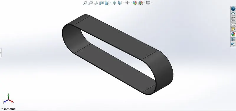
- Transmission belt:
- Isometric view of transmission belt
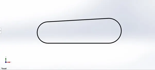
- Front view of transmission belt
kickstand
- Isometric view of kickstand
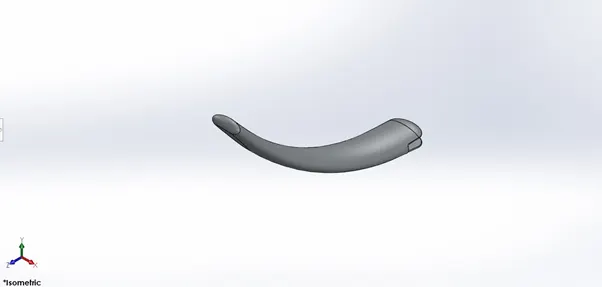
- top view of kickstand
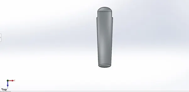
- Left view of kickstand
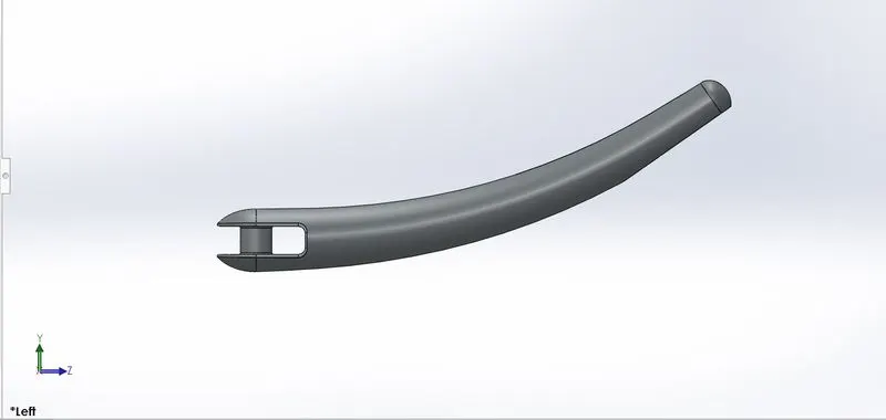
Front fender
- Isometric view of the front fender
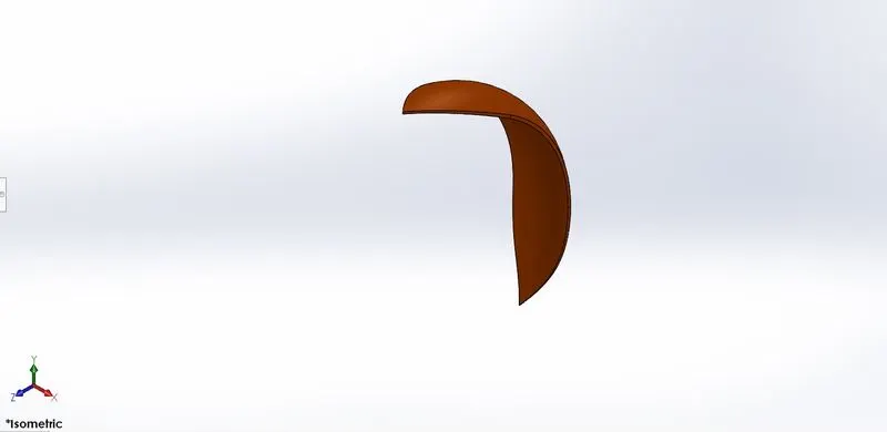
- Front view of the front fender
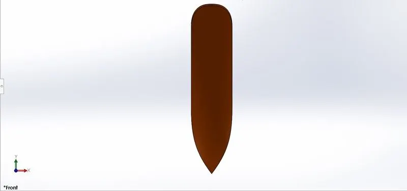
- Left view of the front fender
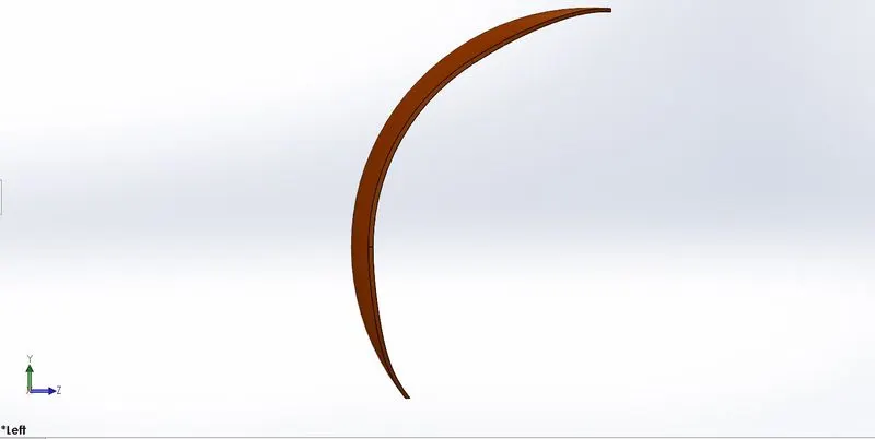
Rare fender:
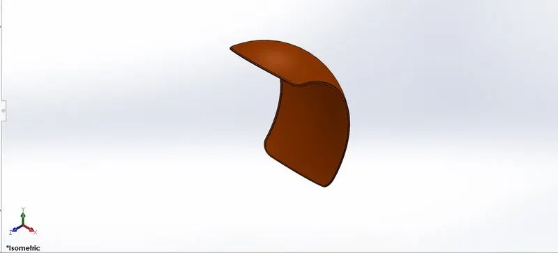
- Isometric view of the rare fender
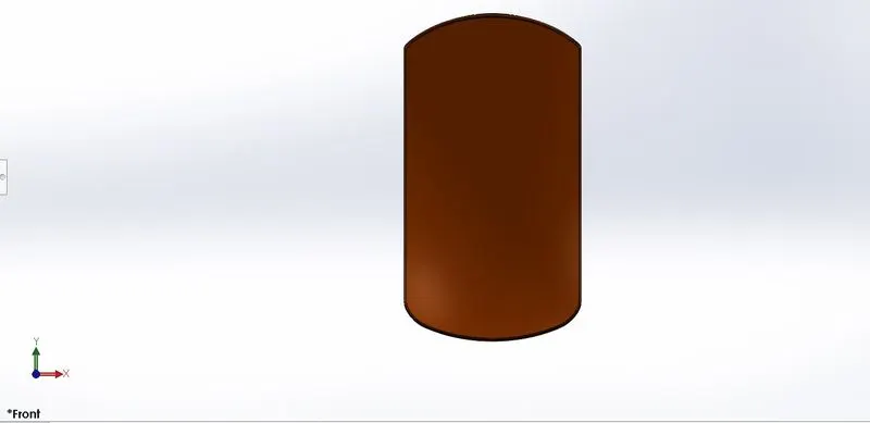
- Front view of the rare fender
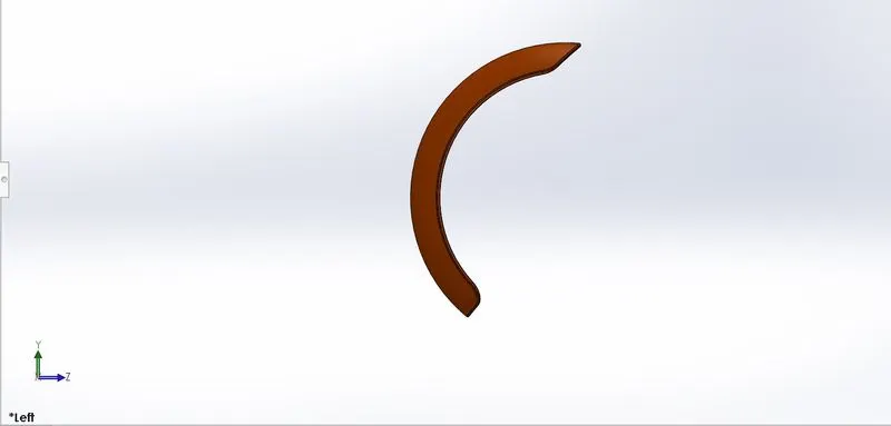
- Left view of the rare fender
Chain:
- Isometric view of a chain
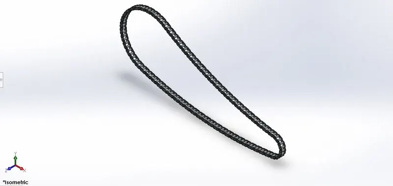
- Front view of a chain
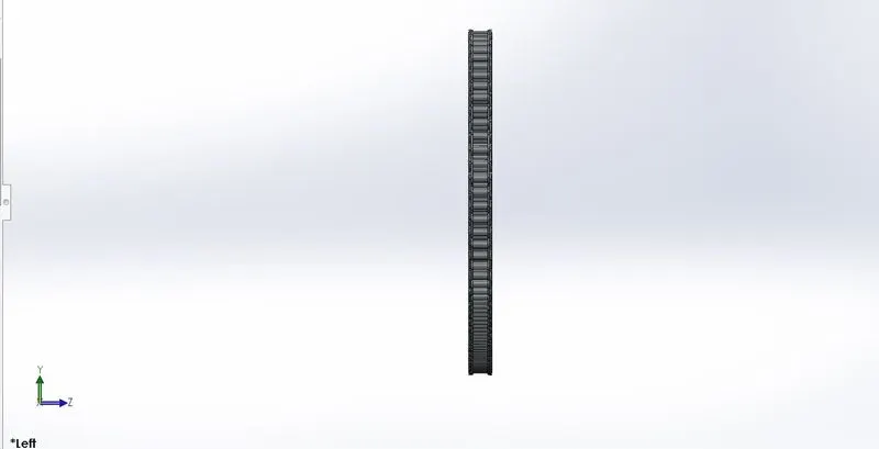
- Left view of a chain
Oil tank:
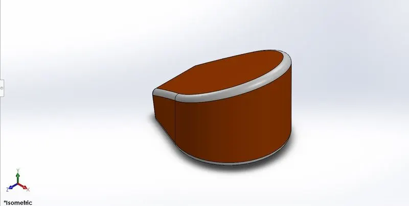
- Isometric view of an oil tank
- Front view of an oil tank
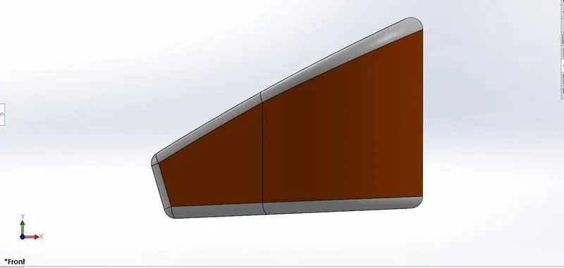
- Left view of an oil tank
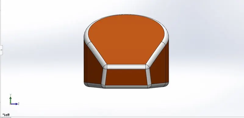
Pedal
- Isometric view of a pedal
- Front view of the pedal
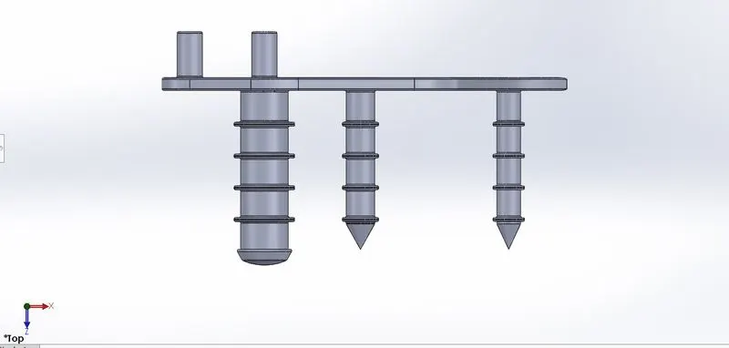
- Left view of the pedal
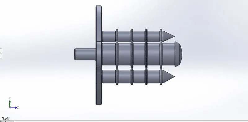
Front-wheel
- Isometric view front wheel
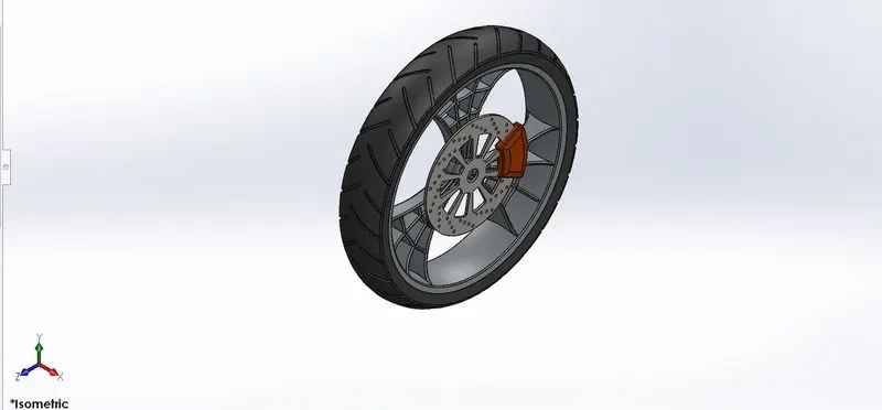
- left view of the front wheel
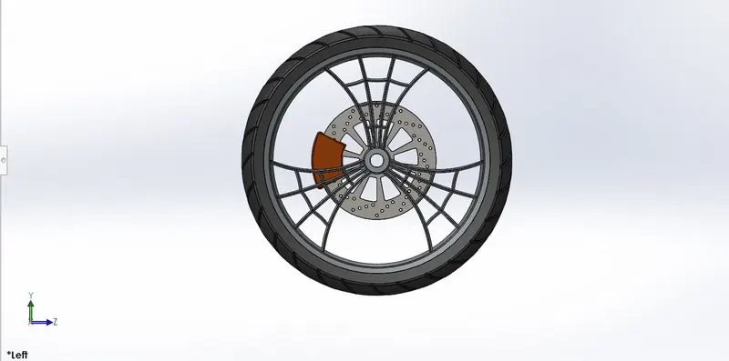
Rare wheel
- Isometric view of the rare wheel
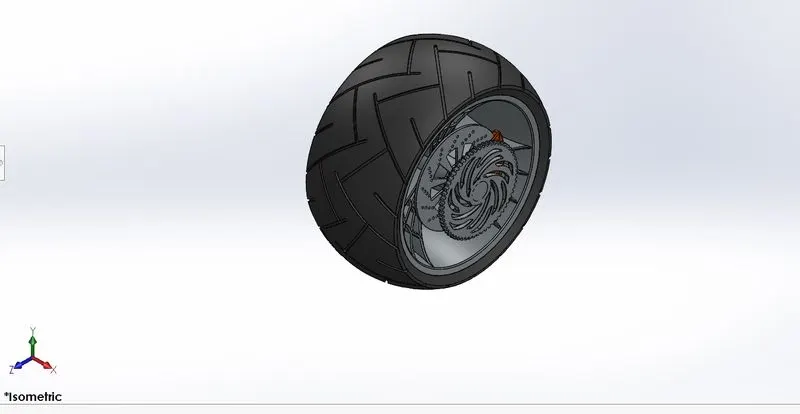
- Top view of the rare wheel
- Left view of the rare wheel
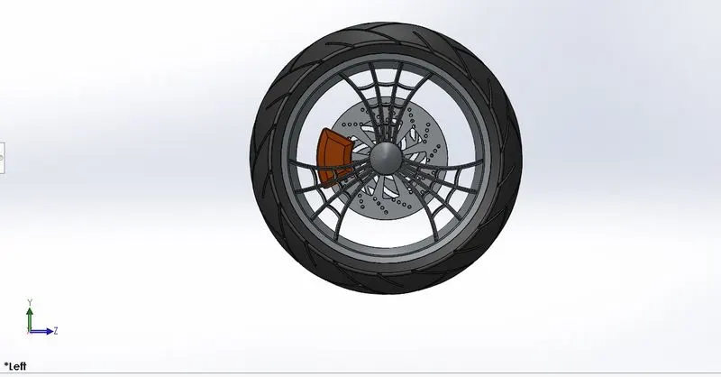
Front fork
- Isometric view front fork
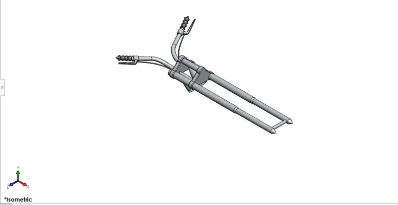
- Front view of the front fork
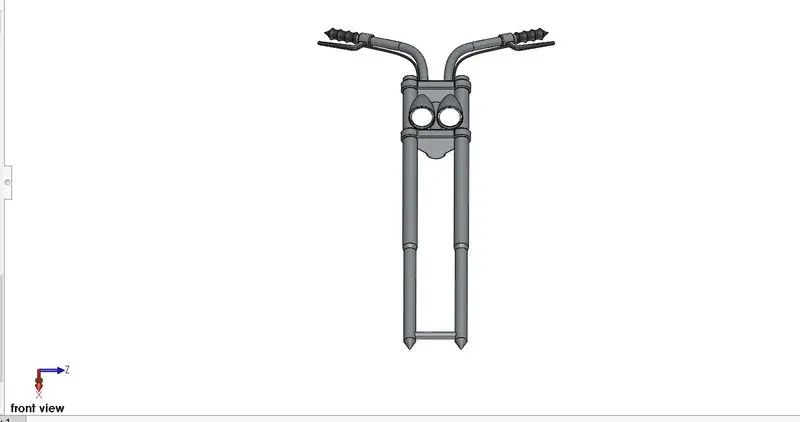
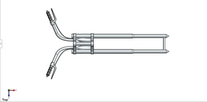
- Top view of the front fork
Chassis
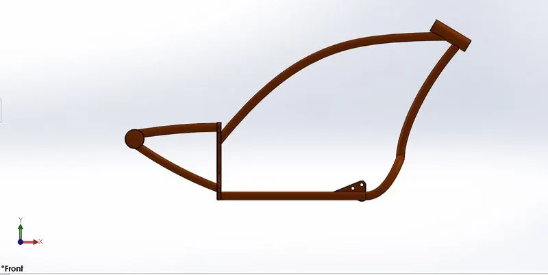
- Front view of the chassis
- Isometric view chassis
Engine:
- Isometric view of the engine
- Left view of the engine
- Top view of the engine
Gas tank:
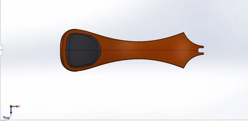
- Isometric view of the gas tank
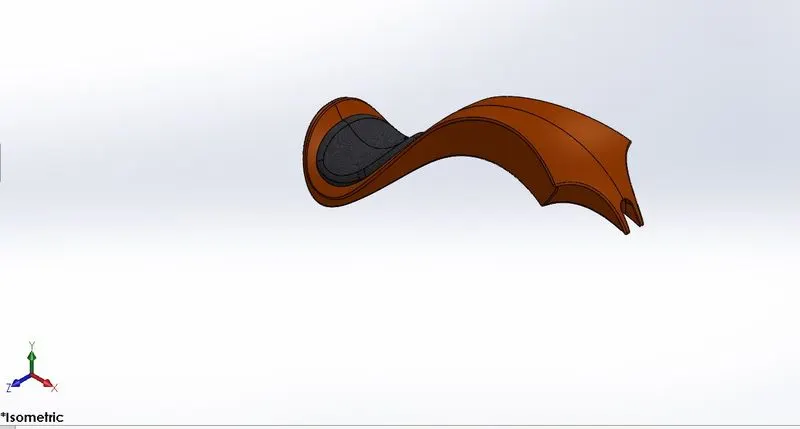
- Front view of the gas tank
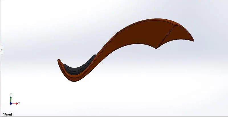
- Top view of the gas tank
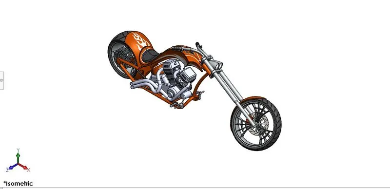
Assembly of a chopper
- Isometric view of the chopper
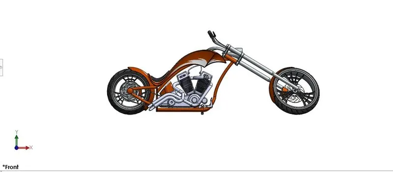
- Left view of the chopper
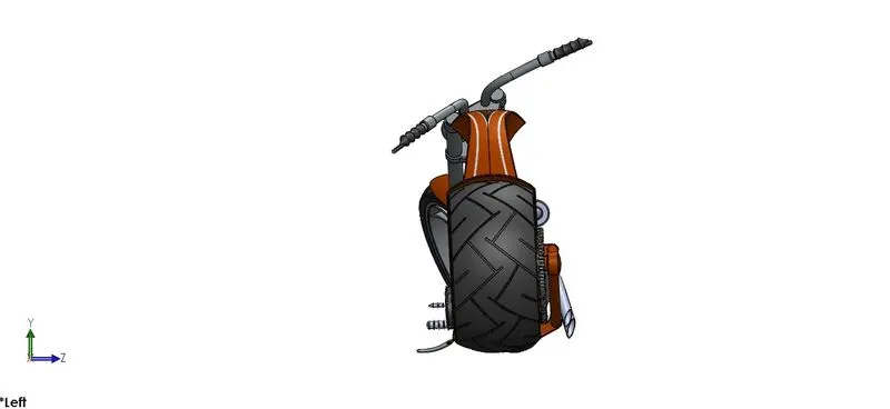
- Front view of the chopper
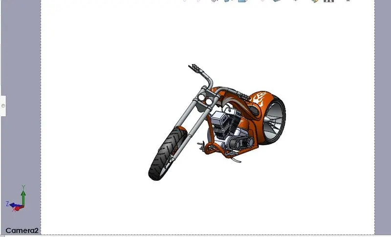
- Camera view of the chopper
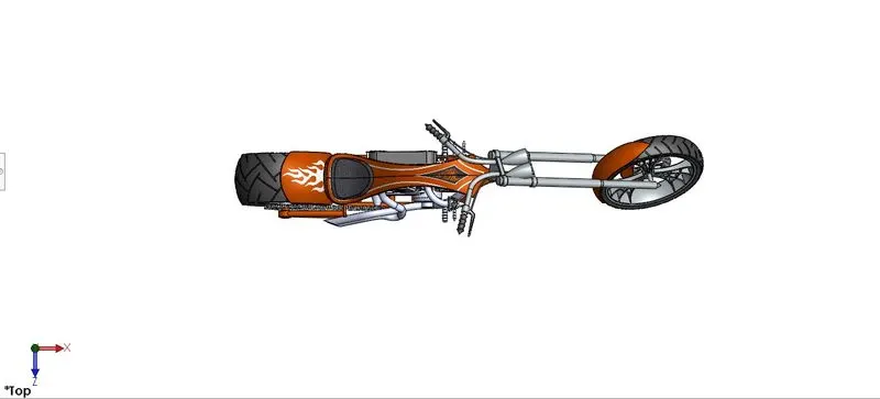
Top view of the chopper
Render images:
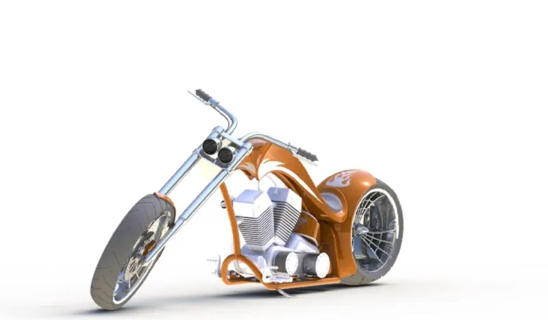
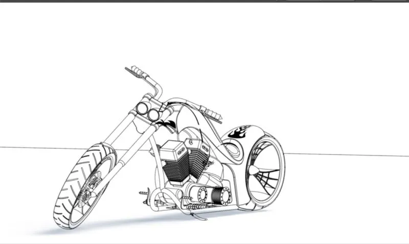
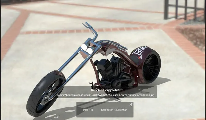
Render
Conclusion:
Learned about how to create parts and assemble an American chopper by using solid works tool, sketches, command manager.