Week 8 - Challenge 2 - Base Bracket Design
AIM-Create the Base Bracket Plastic component through the given Class-A surface. To begin with, the tooling axis for the given Class-A Surface should be created meeting the requirements of the draft angle and at the end perform the Draft analysis on the model.
BASE BRACKET PLASTIC
Draft analysis help to draft part eaisly removable from mold. plastic part angle of draft is 0.5 to 3 degree. in sheet metal part draft angle 7 degree to more. mold part ejection from mould , draft angle to perpendicular .
in base bracket plastic part to study CLASS A SURFACE , CLASS B SURFACE, CLASS C SURFACE
STEP -1
FIRST ALL CHECK SURFACE JOIN
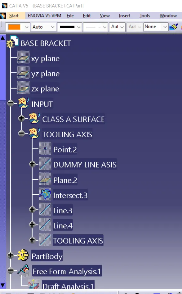
tooling axis-
- tooling axis define the ejection mold direction. tooling axis is z direction.
- create a point on circle and create a dummy line axis .
- dummy line and point help to create a plane
- intersect on plane , CLASS A surface.
- two line create the when ejection of part problem.
- two line bisecting the tooling axis in z direction
step -2
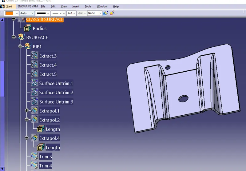
create the CLASS B SURFACE
EXTRACT the rib of CLASS A SURFACE
UNTRIM the all surface
extrapol the surfaces for all sides bisect the other surfaces
trim the surfaces are bisect
three surface to create the rib 1
offset from class a surface thikness of part(2.5mm)
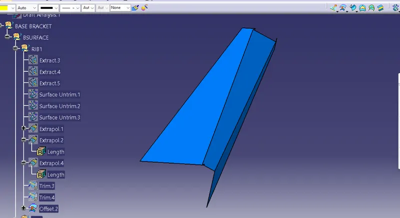
now repeat the same step follow create the rib 2
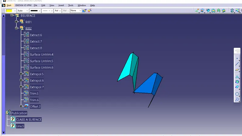
now create the base bracket of part
extract the all surfaces of base bracket
untrim the surfaces
extrapol the sufaces
trim it
offset it 2.5 mm
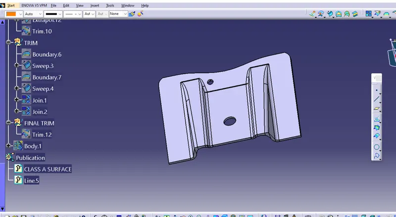
now , geometrical set for final trim for create CLASS B SURFACE
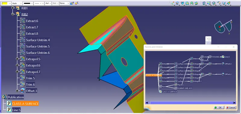
CLASS B SURFACE
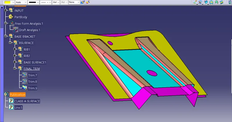
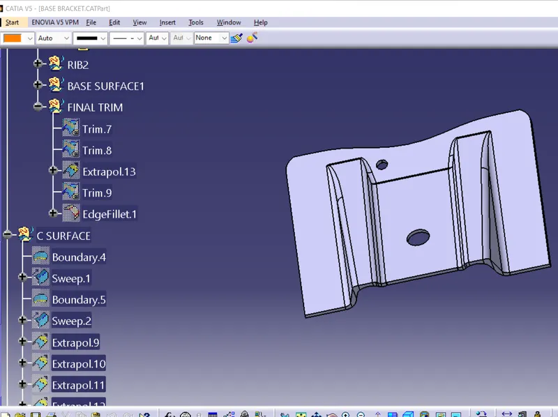
NOW TO CREATE THE CLASS C SURFACE
EDGES TO CREATE THE BOUNDRY
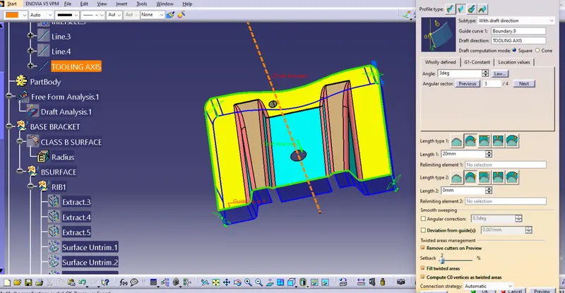
& SWEEP IT 3 DEGREE tooling axis
EXTRALPOL THE ALL SURFACES AND TRIM IT.
TWO HOLES create the boundry and sweeep it tooling axis
join the all surfaces
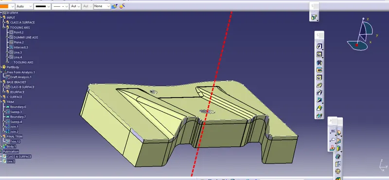
now
class b and class c surface trim it
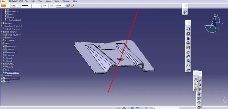
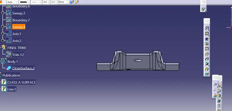
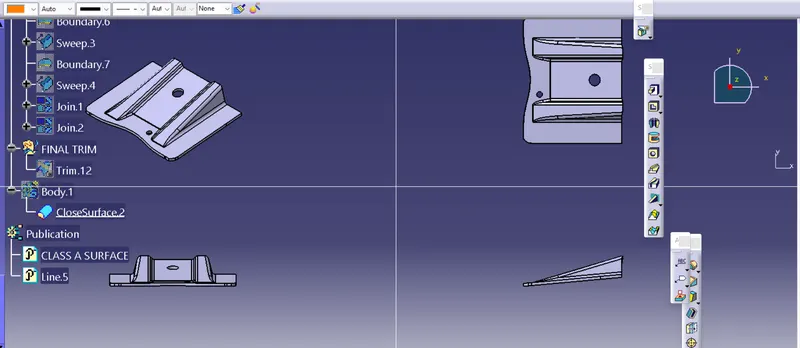
FEATURE TREE
problems-
create the class c surface
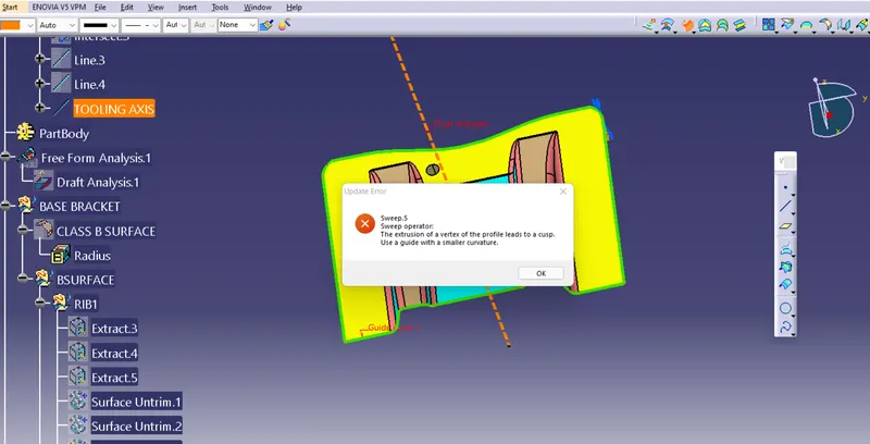
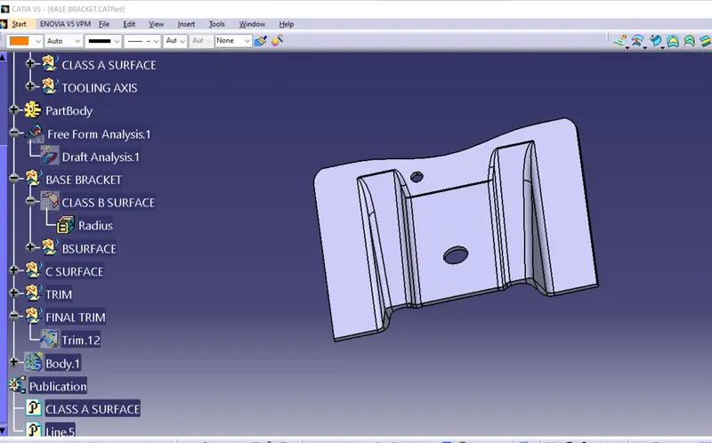
solve
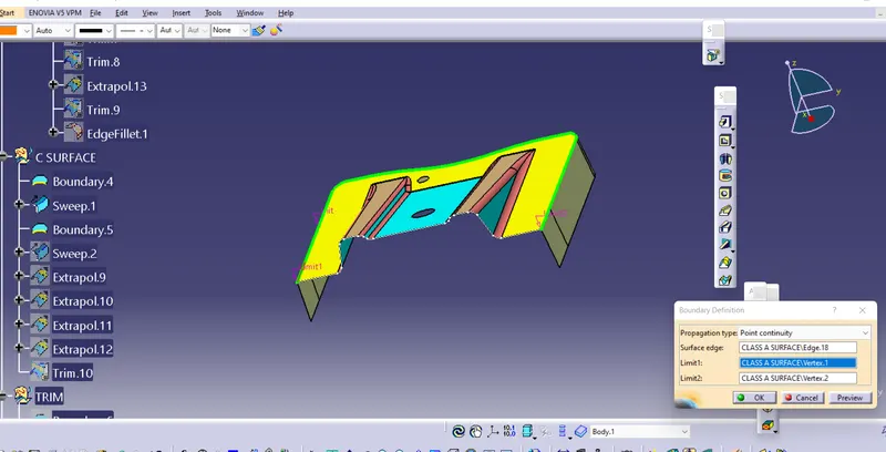
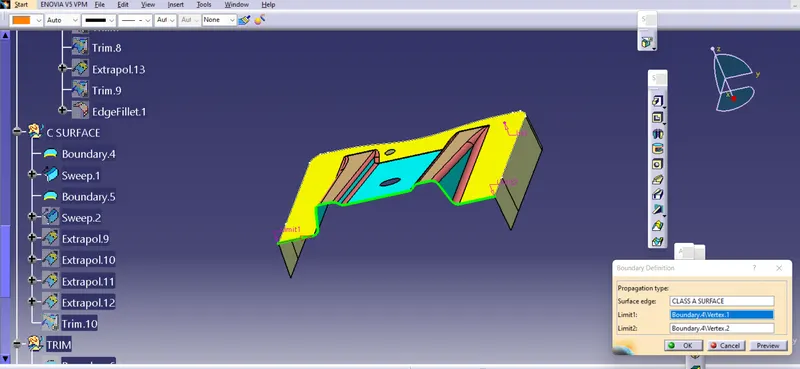
RESULTS- CREATE A SOLID BODY BASE BRACKET DESIGN