Week 8 - Challenge 2 - Base Bracket Design
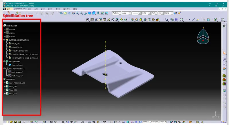
Title- Create the Base Bracket Plastic component through the given Class-A surface. To begin with, the tooling axis for the given Class-A Surface should be created meeting the requirements of the draft angle and at the end perform the Draft analysis on the model.
Objectives-
1. To understand how to generate class B & class C surfaces from input class A surface
2. To understands importance of Tooling Axis
3. To understands importance of Draft & Draft analysis
4. Create solid body using closed surfaces.
Tooling Axis-
In injection molding, cavity and core opens in one direction to remove molded part from it. The direction in which mold need to open is called Tooling Axis. Tooling axis should be clears most of the tapered surfaces of the part to be molded. Plastic part designers will be creating tooling axis by considering these tapered surfaces.
Tooling axis is used in the creation of the Class C surfaces of the part. Class C surface is created by providing draft, so that they can be removed easily from the mold while ejection process. This draft angle is given with the reference of Tooling axis.
Creation of Tooling Axis by Bisecting method-
1. Creation of Dummy Tooling Axis
To create Tooling Axis first we have to create Dummy Tooling Axis.
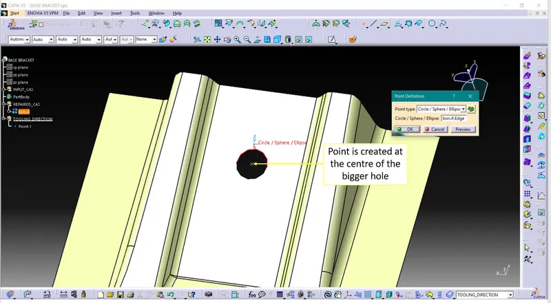
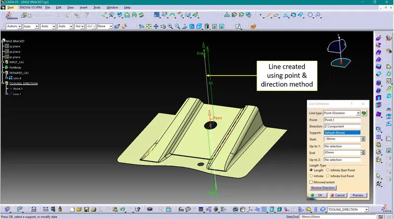
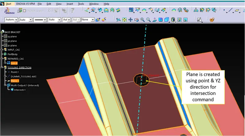
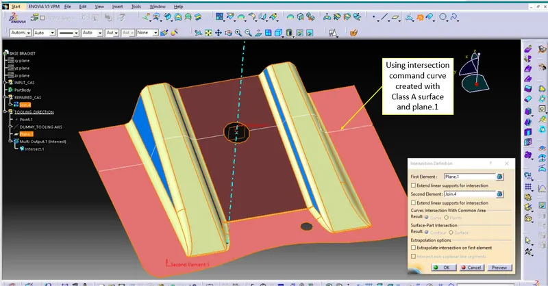

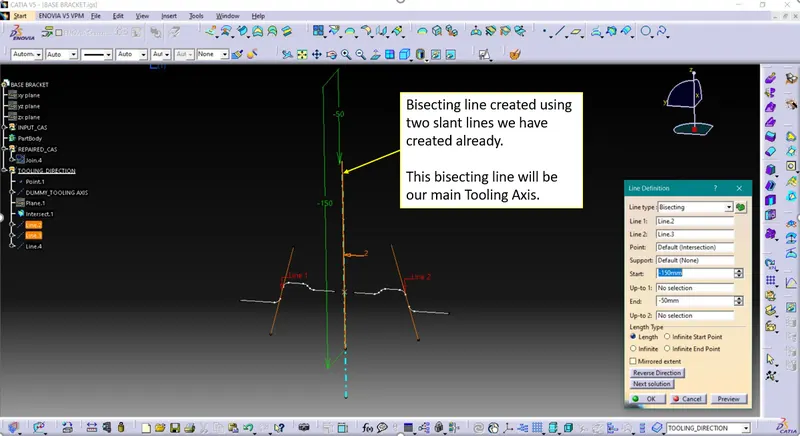
Creation of close surface using Class A, B & C surfaces-
a. Repairing class A surface
Class A surface is aesthetically appealing surface to the observer. This surfaces is created by styling team.
Input Class A surface we received from styling team may have some errors in it. So, we need to find what are the errors, correct those errors and create single surface using join command after repairing it.
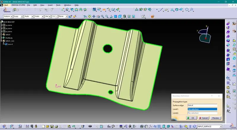
It will be more helpful if we give surfaces different color codes & publish this Class A surface.
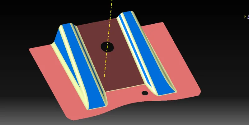
b. Creating Class B surface
Class B surface will be holding all engineering features like ribs, screw bosses, etc.
We need to create CBS(Class B surface) using CAS(Class A surface). The process of generating CBS is explained below-
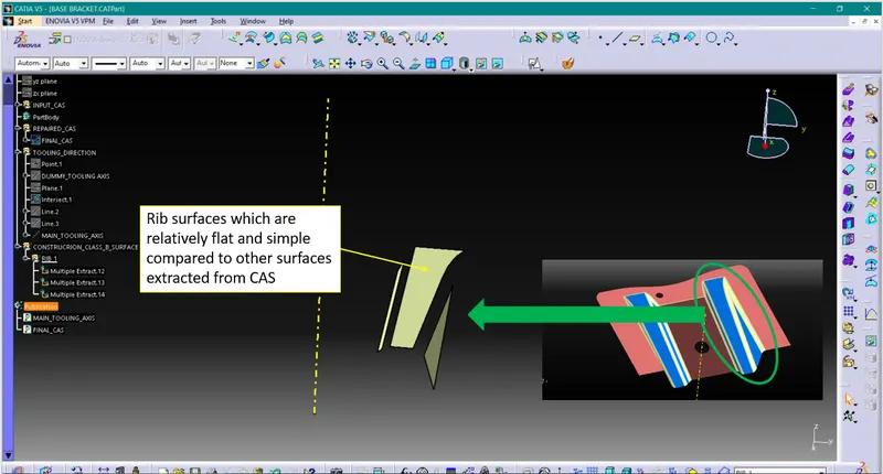
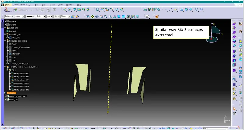
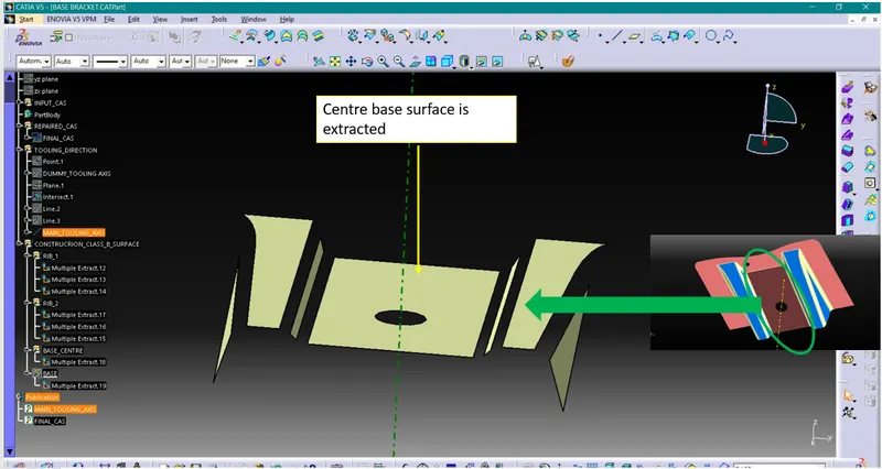
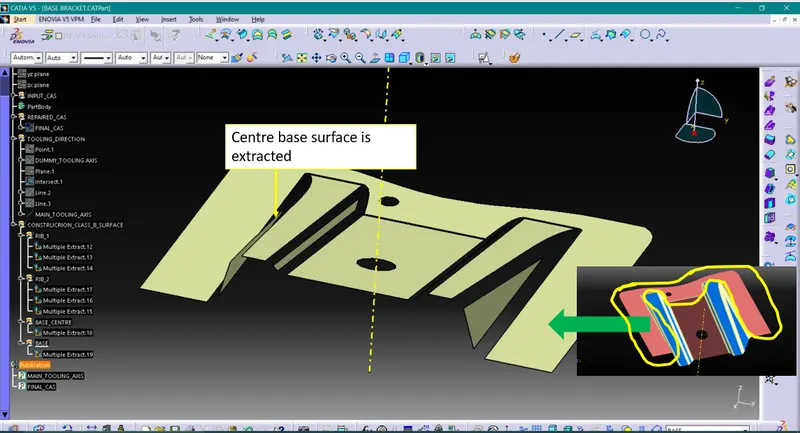
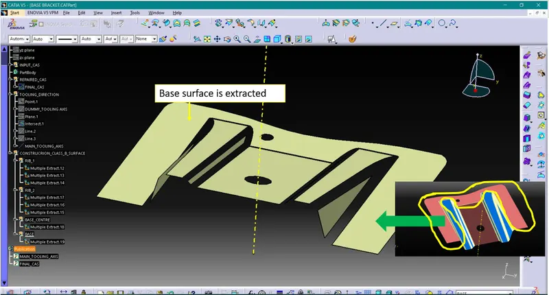
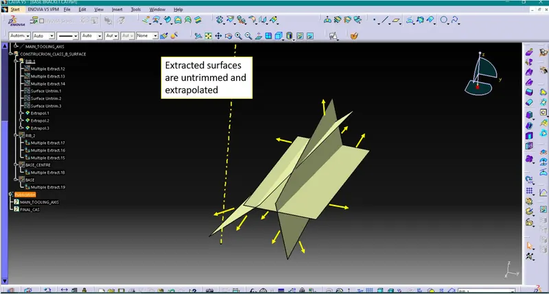
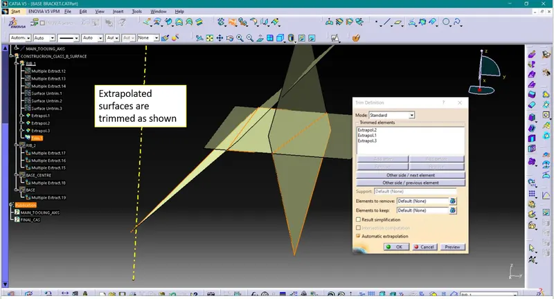
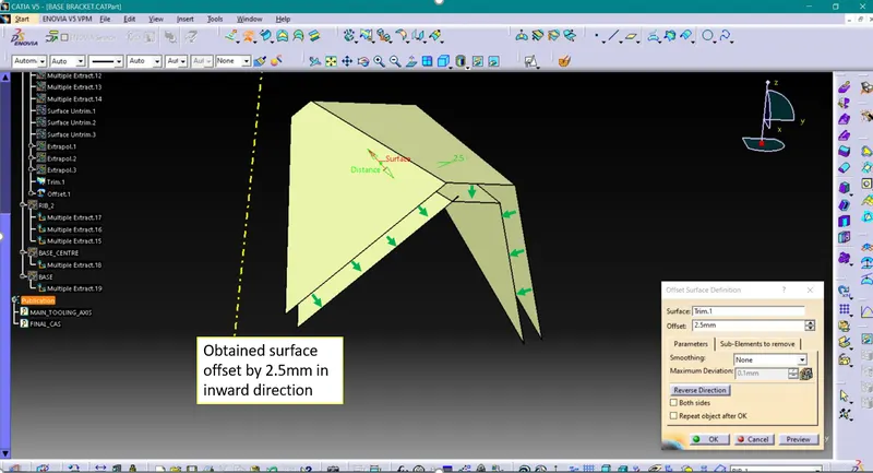
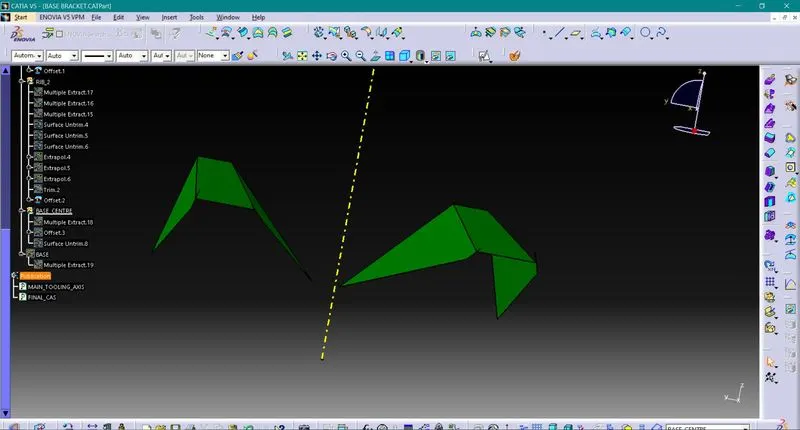
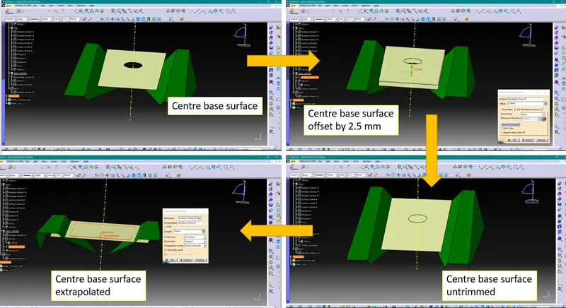
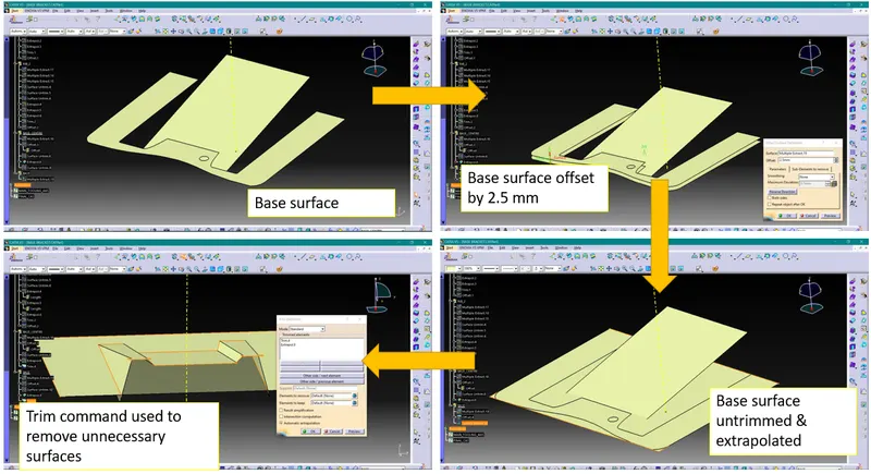
c. Creating Class C surface
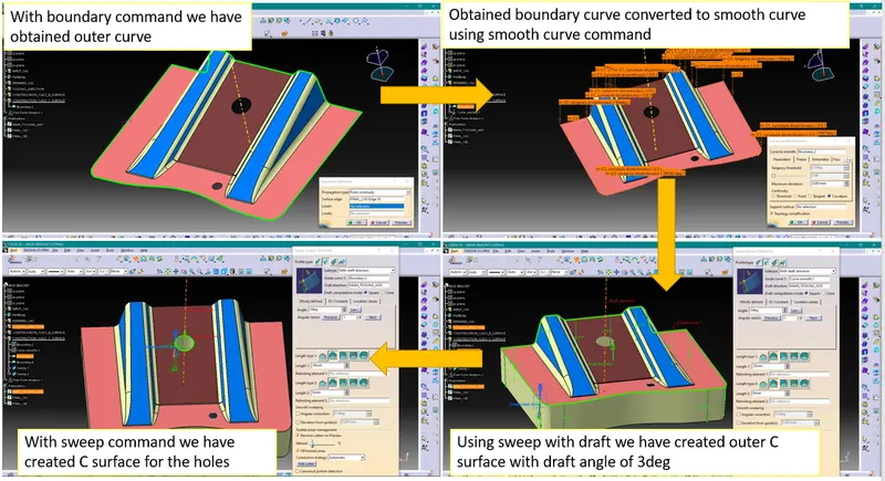
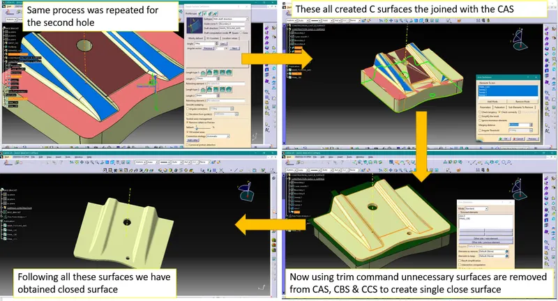
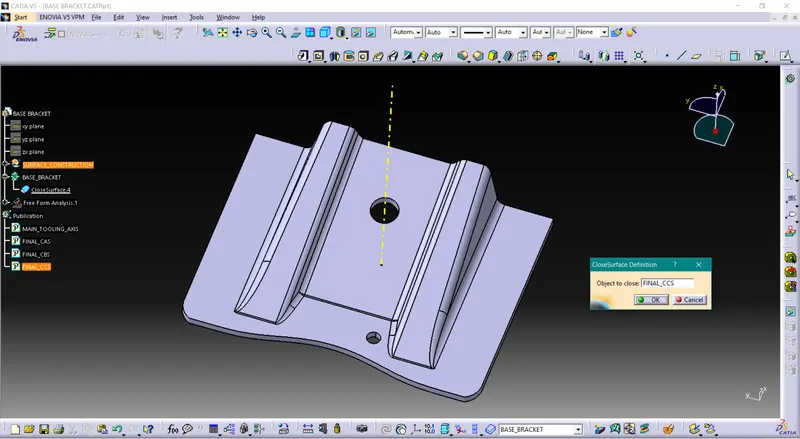
d. Creating solid body using close surface
Creating solid body requires completely closed surfaces or otherwise it will show error.
Draft Angle-
With plastic injection molding, it is important to design for manufacturability. To do this, you must take every step of the process into consideration, including ejection from the mold. Even though the part may form correctly in the mold, problems can arise during the ejection of your part. A draft angle will help avoid most of these issues.
What is Draft Angle?
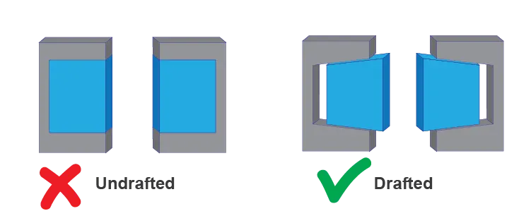
A draft angle is a slant that is applied to each side of most features of an injection molded part. The angle, which is positioned to run toward the direction of a mold’s pull and parting line, helps with releasing the part from the mold. It is rare that a component of a part does not need to be drafted. These cases may include certain low-friction materials, such as some grades of nylon, or specific features, such as crush ribs. However, 99% of the time, you will need to design draft into your part to have the best chance at success with your injection molded part.
Importance of Draft Analysis-
Having easier ejection from the mold may seem like a minor concern, but draft is crucial to manufacturing parts that meet your quality standard. Without draft, major problems can arise in the injection molding process that increase the time and cost of production.
When no draft is designed into the part, problems can come from friction and vacuums. These issues can damage both your part and even your mold in extreme cases. These problems are a direct result of having insufficient draft. Because plastic shrinks as it cools, portions of the part may pull away from the mold while others grip the core. If there is no draft angle that allows a simple push from the ejector pins to pop the part out of the mold, the part’s surfaces will often drag along the mold as it is being ejected. This friction between the two surfaces can cause scratches or gouges in your part and affect the appearance. This is particularly troublesome if your part is being molded with a surface finish or texture. The friction will scrape away texture and leave you with many rejected parts.

In addition to friction, no draft presents the possibility of a vacuum forming during ejection. If the sides of a feature cannot release from the mold, the ejector pins may push on the section until the vacuum becomes so stressed that the part may bend, break, or warp by the time it is pushed out. The alternative is that the part becomes stuck in the mold if the ejector pins are not strong enough to overcome the vacuum. A higher ejection force would be needed to remove a part without draft, which means the part would need to cool longer before it can be ejected successfully. This increase in cycle time and the likelihood of having more rejected parts overall will drive up your production costs.
By adding draft angles to your design, you can avoid these problems and lower the cost of production. Draft will allow parts to release from the mold with ease, which will result in better cosmetic finishes and fewer rejected parts. In addition, draft can help you avoid costly elaborate ejection setups.
Draft Analysis-
The Draft Analysis command enables you to detect if the part you drafted will be easily removed.
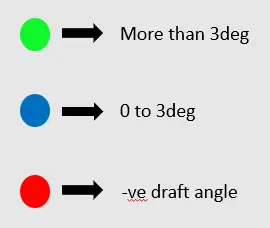
This type of analysis is performed based on color ranges identifying zones on the analyzed element where the deviation from the draft direction at any point, corresponds to specified values.
Process of performing draft analysis in Catia V5-
1. Click on the draft analysis icon ( ) or go to Insert>Analysis>Feature Draft Analysis
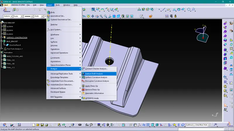
Note- While doing Draft analysis make sure you are enabling material view mode.
2. Switch on quick analysis mode by clicking on below highlighted icon
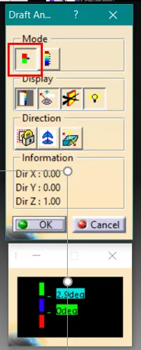
3. Selecting Draft Direction
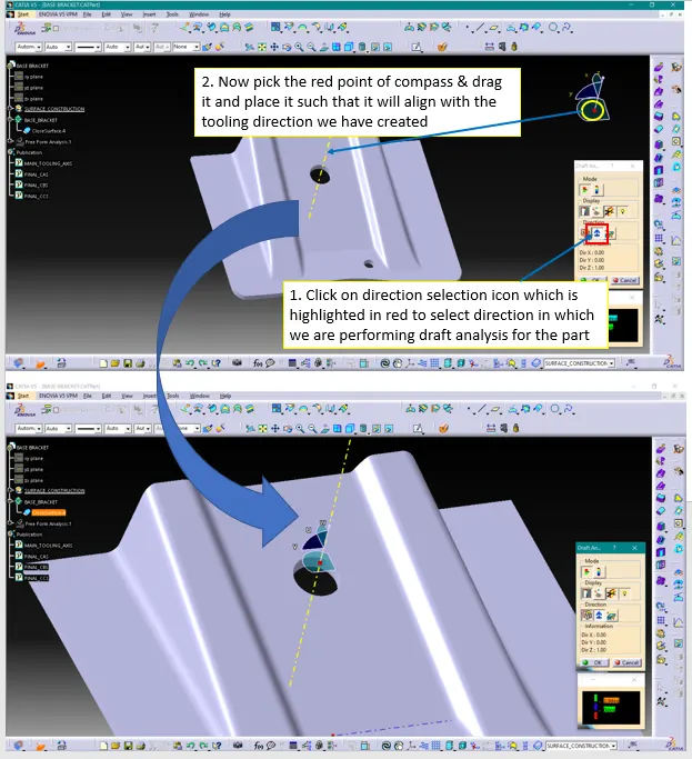
4. Selecting surface
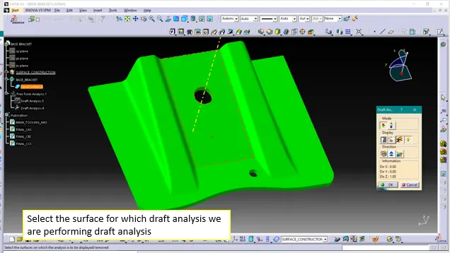
5. Input the draft angles
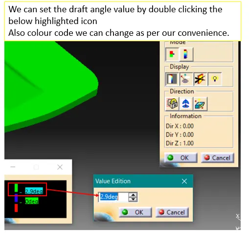
6. Running point
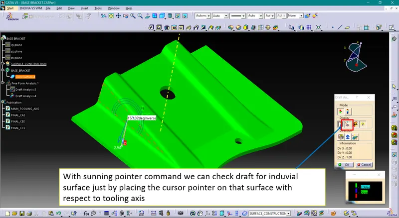
Draft analysis for CAS-
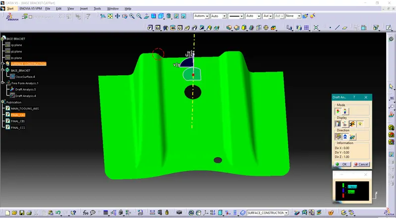
The above image shows that our CAS is found ok in draft analysis
Draft analysis for Solid part-
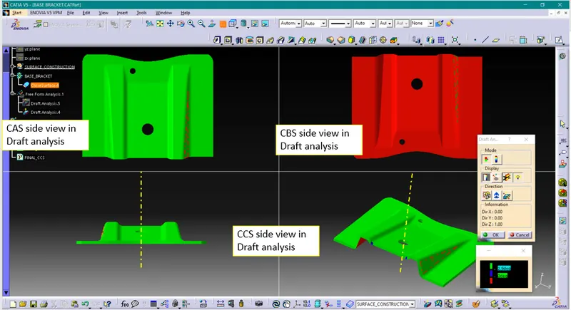
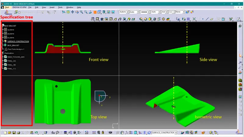
Solid model with the proper color code of the draft angle in various orientations (Isometric, Front, Side, and Top View)-
Conclusion-
1. We have understood how to generate class B & class C surfaces from input class A surface
2. We have understood importance of Tooling Axis
3. We have understood importance of Draft & Draft analysis
4. We have created solid body using closed surfaces.