Week 8 - Challenge 4 - Coin Holder Design
COIN HOLDER
CLASS A SURFACE
THICKNESS : 2.5mm
Process to be carried:
Initial step is to visually analyse the given CLASS A SURFACE and find the tooling axis direction and the sides that are to be drafted.
Consider a tooling axis at the middle surface directed normal to the surface for the given Class-A Surface should be created meeting the requirements of the draft angle
Change the colour of the given component with different colors to identify each stage of walls and faces.
Start extracting the faces one by one from the class a surface, Let's start with the side walls and then to the upper walls and then to the base atlast to the inner area.
Using EXTRACT command, extract the faces.
Untrim the extracted faces
Extrapolate each face to get an intersection between them.
Trim the intersected faces (Trim the faces accordingly to obtain the required shape)
Offset the obtained shape to the thickness of the component to be designed (In our case the thickness of the component is 2.5mm)
Follow the same steps for all other parts to form the B SURFACE.
After forming the B Surface, We have to design the C SURFACE
Extract the boundary from the Class A Surface.
To get the C SURFACE, check whether the surface is parallel or perpendicular to the tooling axis.
If it is parallel to the tooling axis, The swept that is created to be drafted in order to the tooling axis where the nominal draft should be of 3 degee.
If it is perpendicular to the tooling axis, The swept should be made 90 degree (perpendicular) to both Class A Surface and Class B Surface.
Then trim the Class C Surface with both the Class A Surface and Class B Surfaces.
Check whether the obtained surfaces are completely closed and it is a single part.
Solid Part:
To convert the obtained surface into solid, Open the Part Design
Use the Close Surface option and then hide the surface.
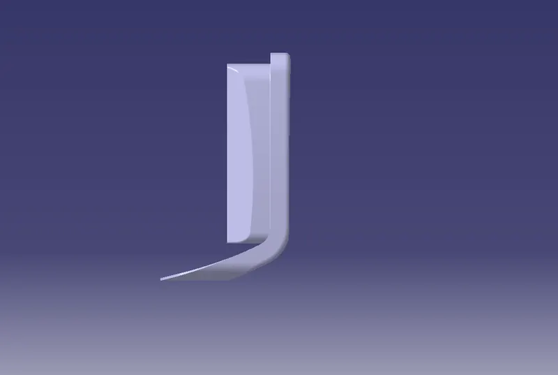
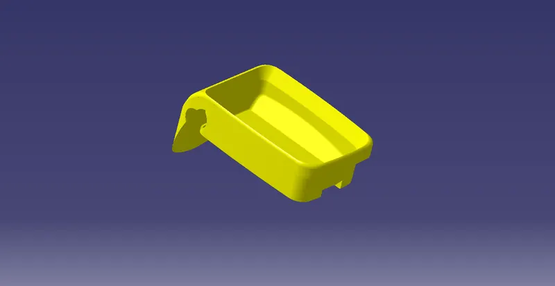
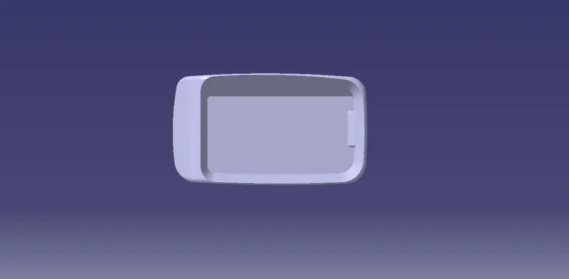
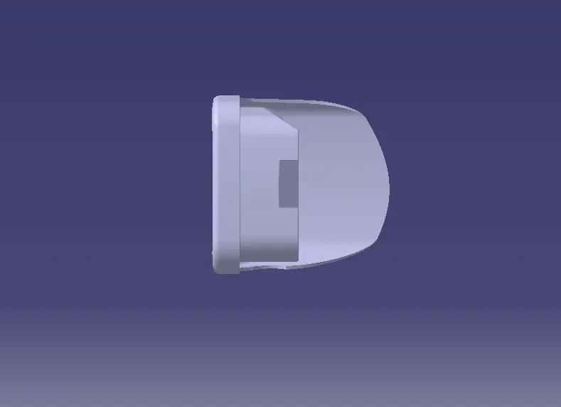
Draft Analysis:
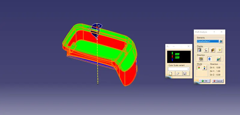
Perform a Draft Anlysis to the obtained solid having the minimum draft angle to be 3 degree