Base Bracket Design using CATIA V5
AIM :
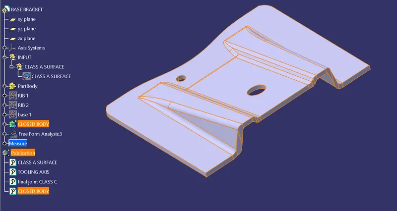
To Create the Base Bracket Plastic component through the given Class-A surface. To begin with, the tooling axis for the given Class-A Surface should be created meeting the requirements of the draft angle and at the end perform the Draft analysis on the model.
PROCEDURE :
First we have to check the connectivity of Class-A surface.for that we use JOIN option to check how well it is connected,with the joint option once after selcting the component it will let us know if there are any surface gaps in the class A surface.
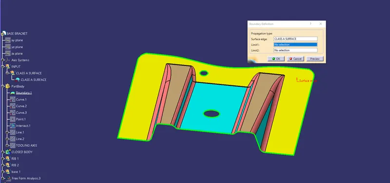
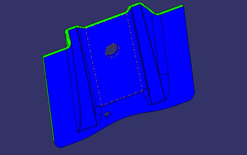
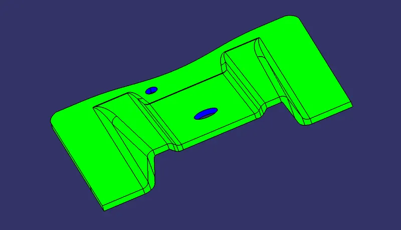
the other way to check the connectivity of the surface is by using BOUNDARY option. with the boundary as a tool,once after we select the component it will create a singe boundary set in the borders of class A which is higlighted in green as shown below,this kind of boundary forms only when there is no discontinuties or gaps on the surface.
otherwise it will create discontinued borders around the parameters of class A surface.So if the surace is properly joined it will create a single boundary which includes the free all the crossectional edges.
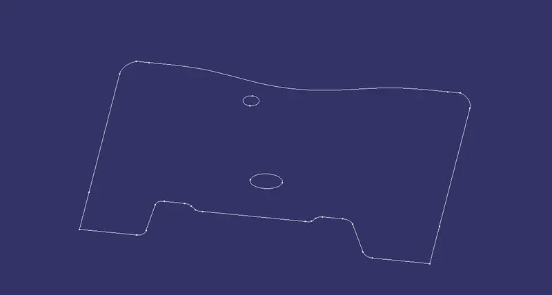
later we diassemble the single boundary into no of actual boundary objects .
TOOLING AXIS :
Now the main concept begins which is finding the tooling axis for the component.Tooling axis defines the mold or core and cavity opening direction. we should create a tooling axis in such a way so that it should cover most of features,holes,geometries and most of the crossectional area.
we will check now the best suitable tooling axis direction through visual inspection of the model with naked eye along all the three axis directions X,Y and Z.
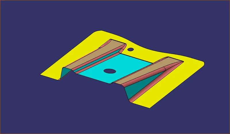
from the model image down below we can observe that if we give the tooling direction normal to the hole it will cover all the geometry and so we can proceed to design the B and C surface and then create a tooling for this base bracket.
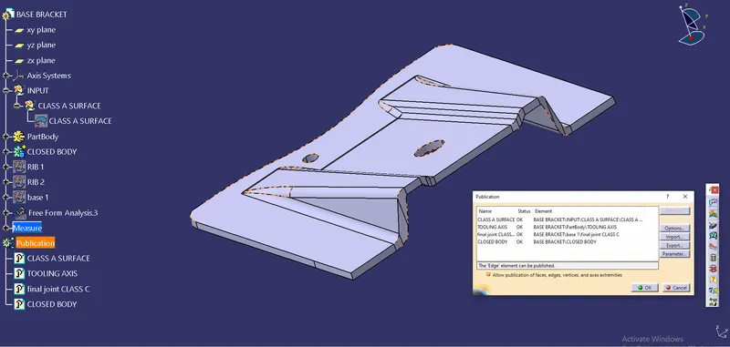
Here we are checking the boundaries to make sure there are no discontinuities or gaps between surfaces and extracting them so that we can use them for tool axis designing and class c designing purpose.
since we have extracted boundary it comes as one entity we have two seperate all the sub boundaries inside it which is two holes .that we can do it untrim or dissamble command.
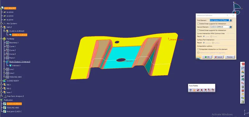
now we are going to intersect the class-A body with YZ plane so that we can use the lines of intersection to create tooling axis with bisection method
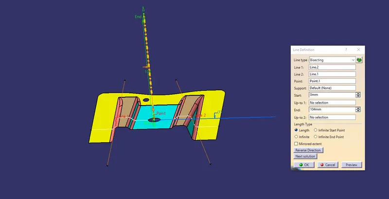
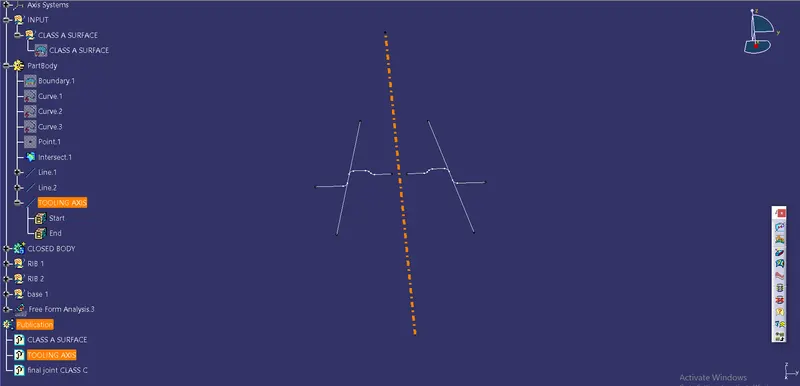
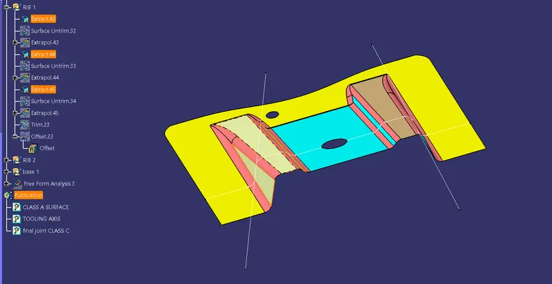
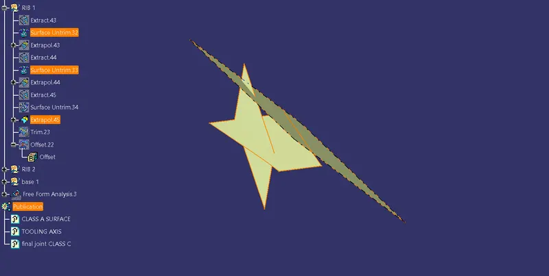
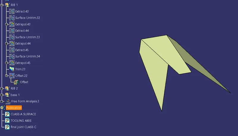
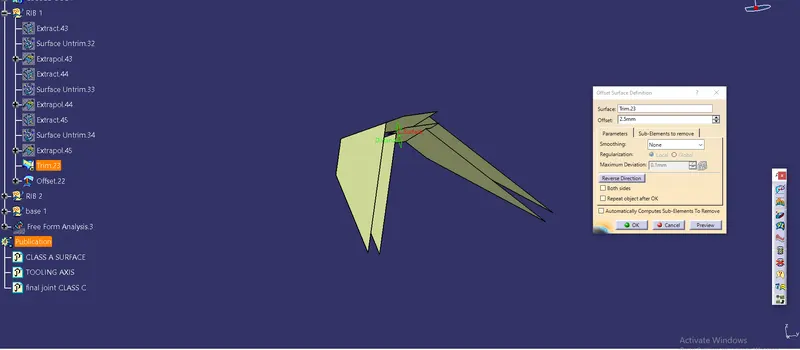
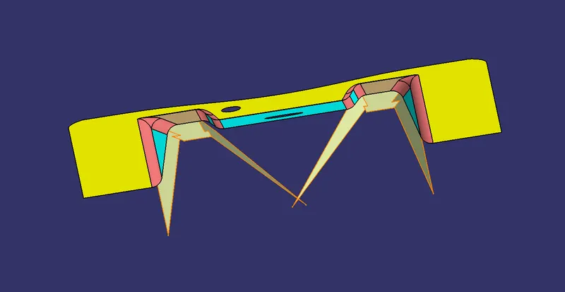
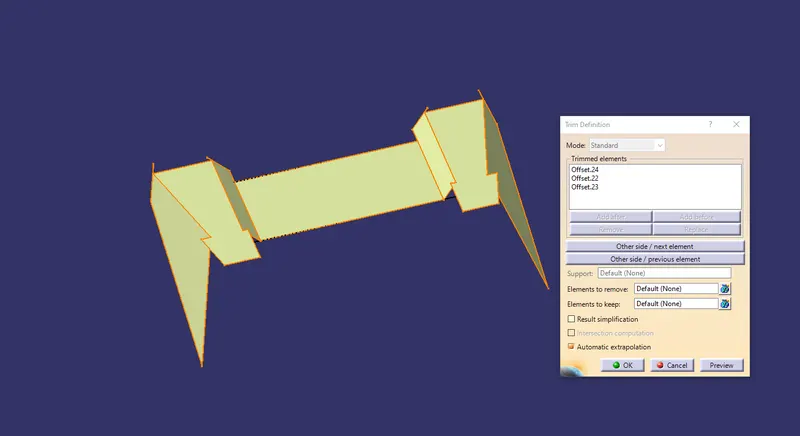
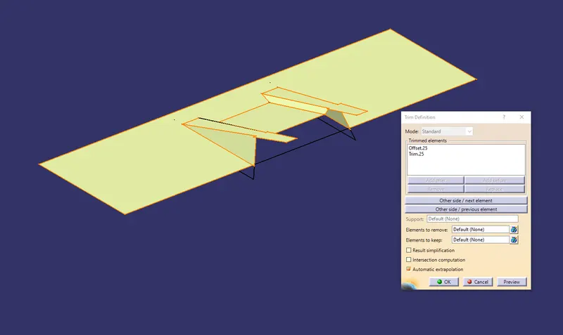
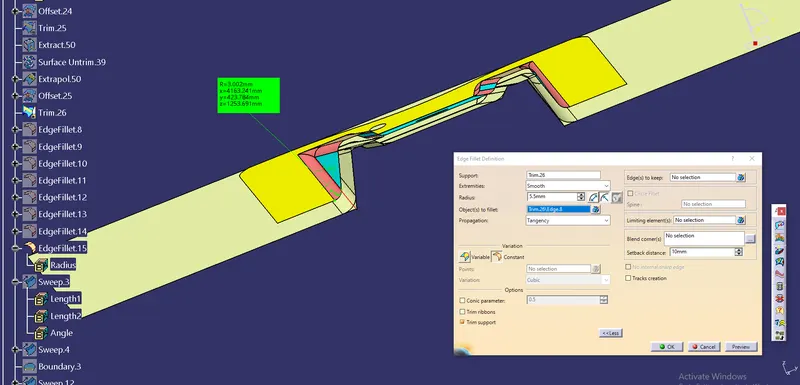
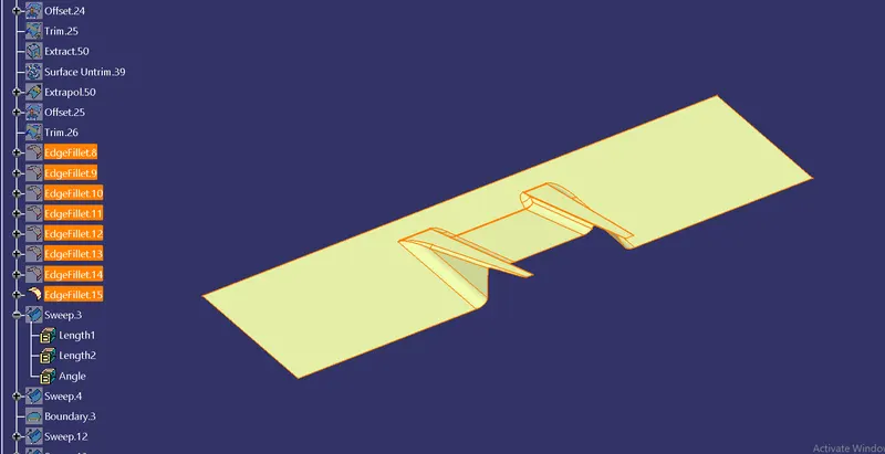
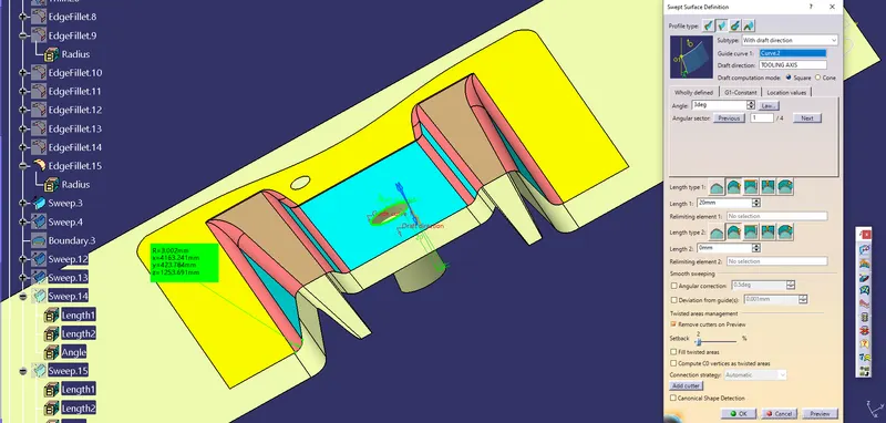
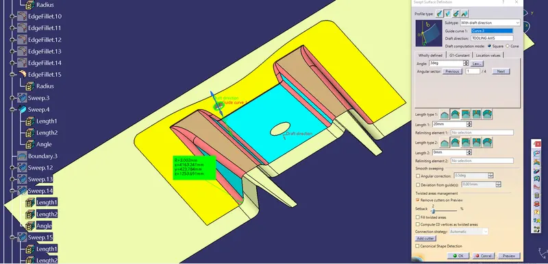
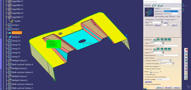
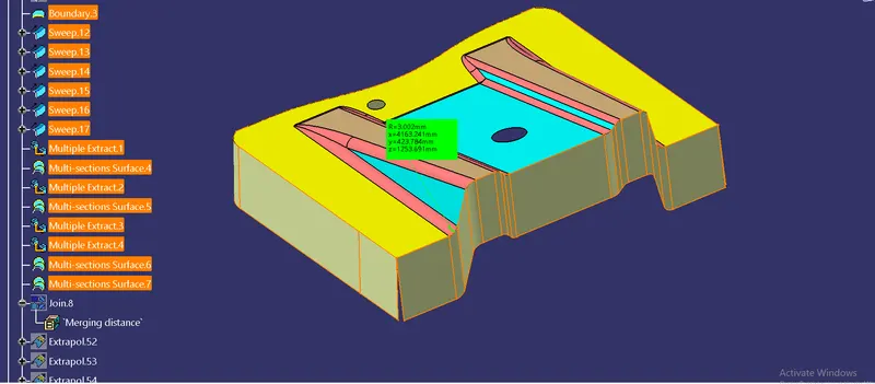
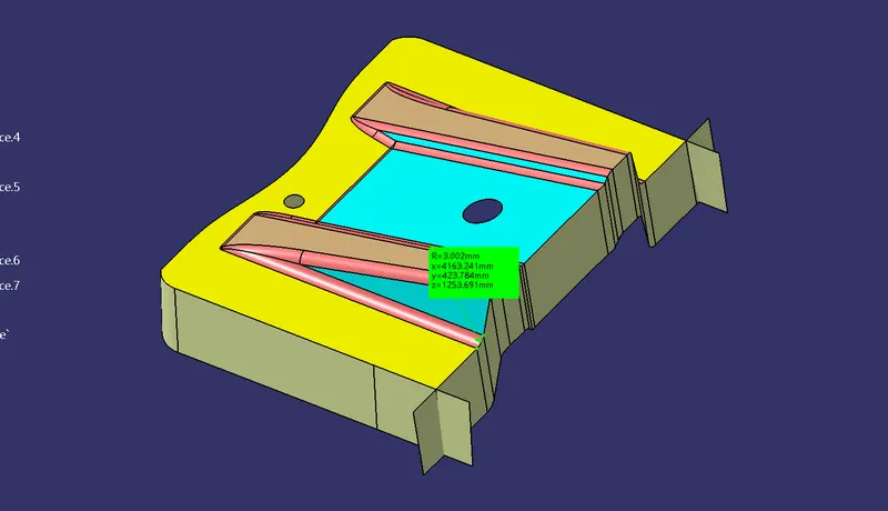
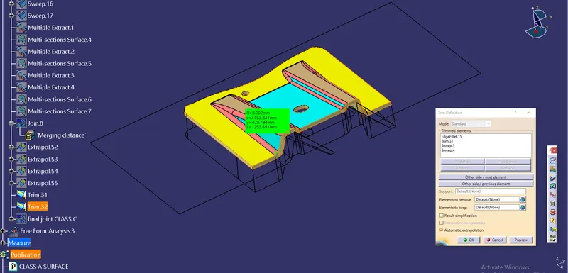
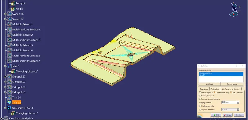
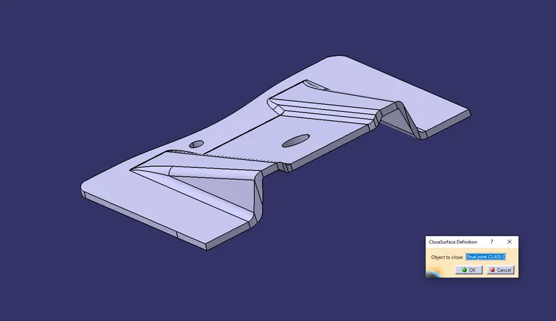
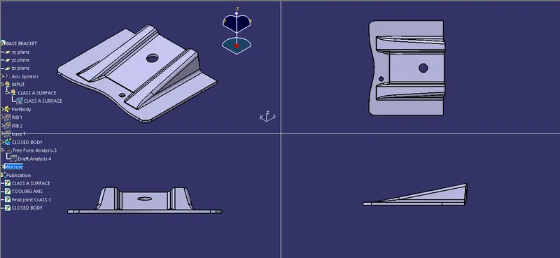
So finally we have made B and C surface from class following the tooling direction that we have created before using bisection method to lines. now its time for draft analysis to take on for that we have to shift the material mode.The visualization mode should be set to Shading With Edges in the View > Render Style command.
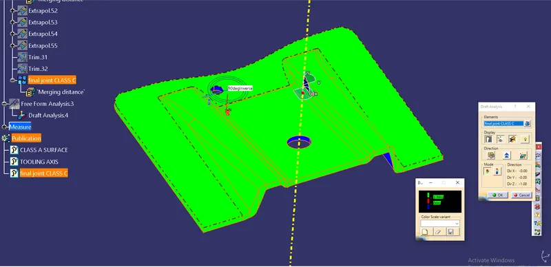
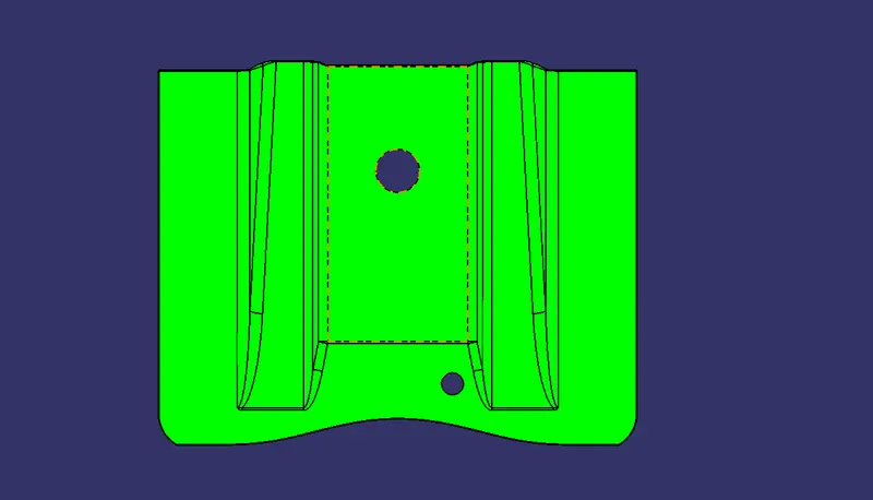
- Screenshots of the solid model with the proper color code of the draft angle in various orientations (Isometric, Front, Side, and Top View)
RESULT :
1.Class B and Class C is made out of the given Class A using PART and Generative shape design workbench.
2.Created Tooling axis with the help if bisection methoid
3.Performed Draft analysis and resolved the errors.