Week 8 - Challenge 2 - Base Bracket Design
Class B Surface
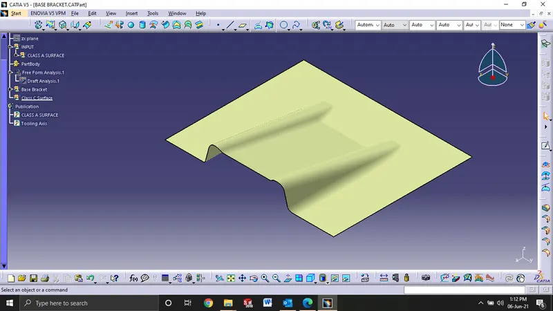
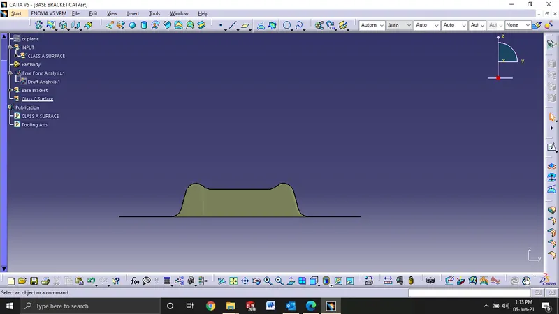
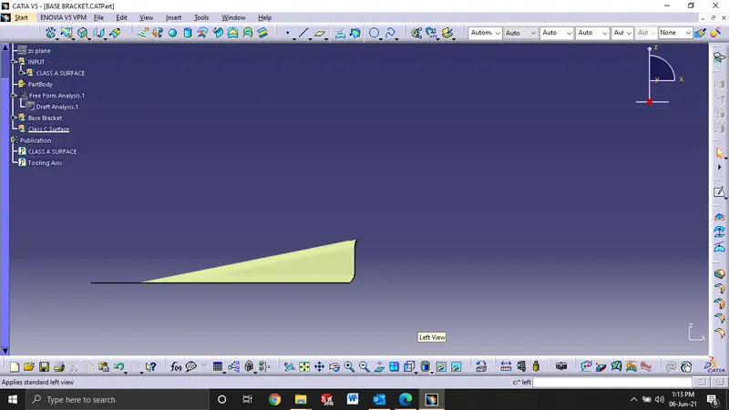
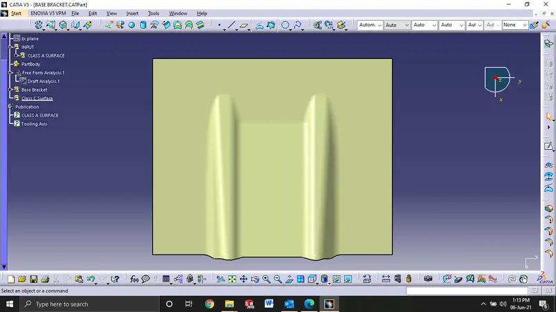
Class C Solid Body
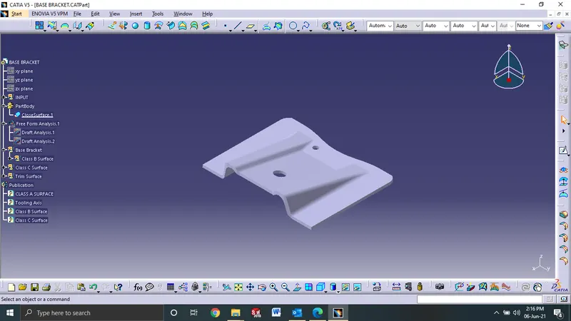
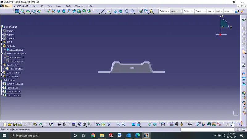
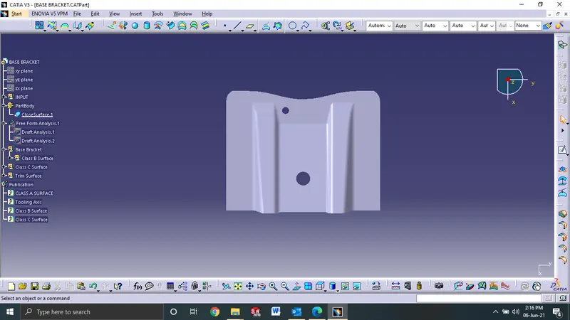
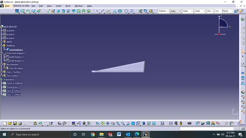
Class C Draft Analysis
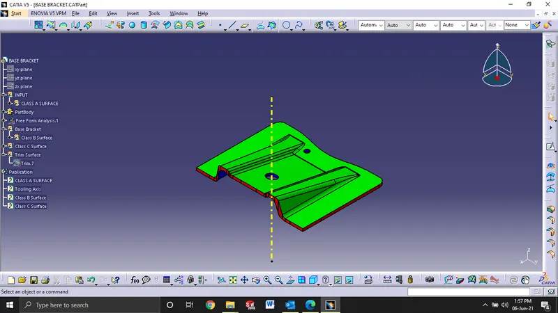
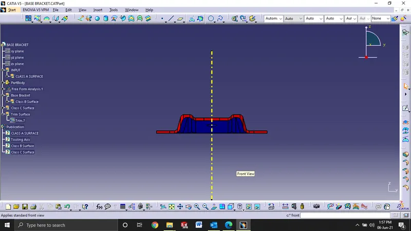
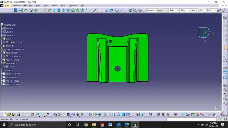
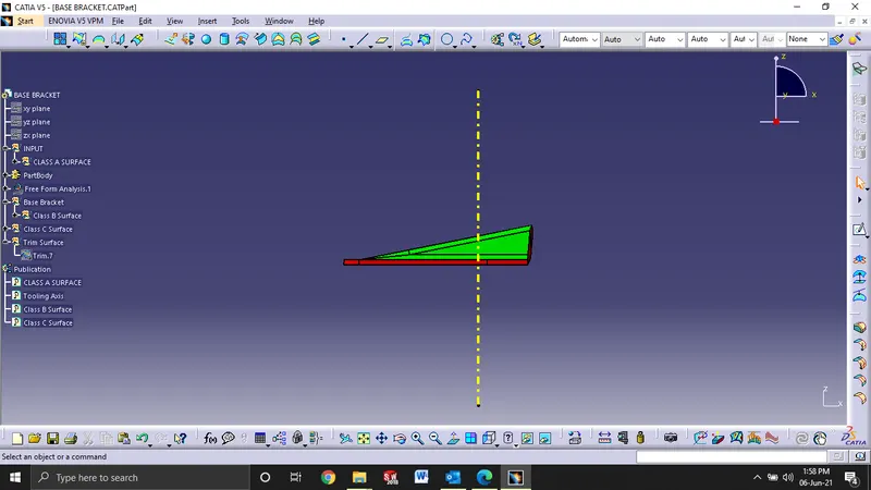
Draft Analysis and Tooling Axis Creation
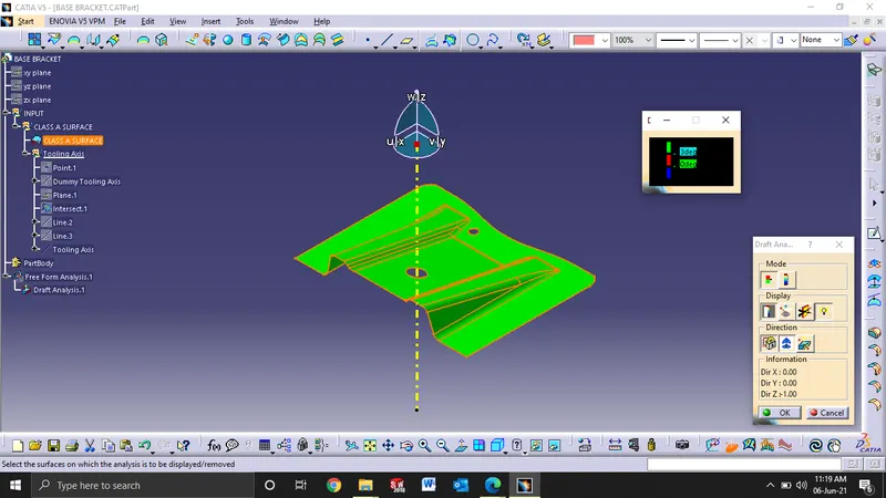
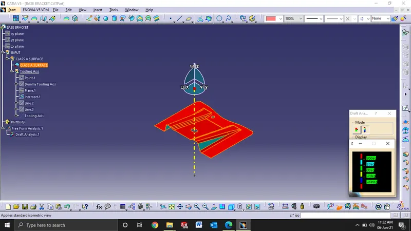
On the class A Surface we have take the holes as a refference for tooling axis.
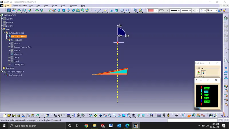
Firstly, a plane is taken in reference to the XY plane on the centre point of the top hole.
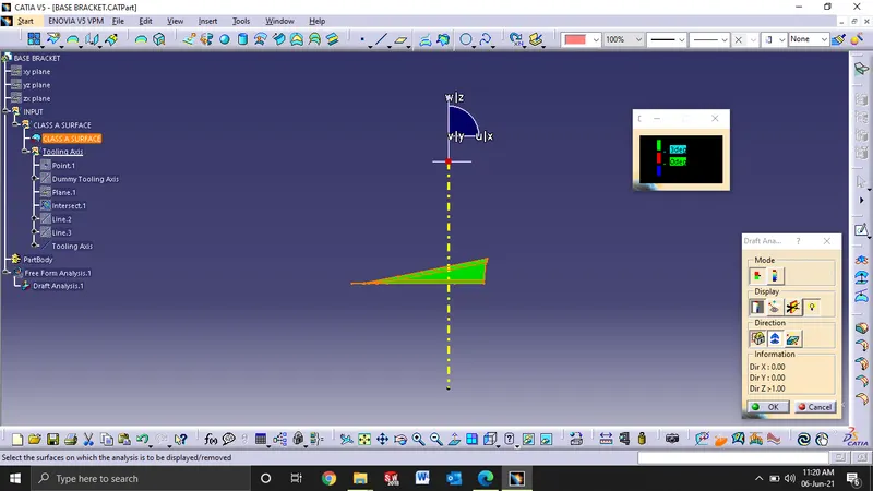
The intersection is done with the plane and the class A surface to get our required geometry for tooling axis creation.
Two angular lines are created using point-point reference and then our final tooling axis is created using the bisecting command.
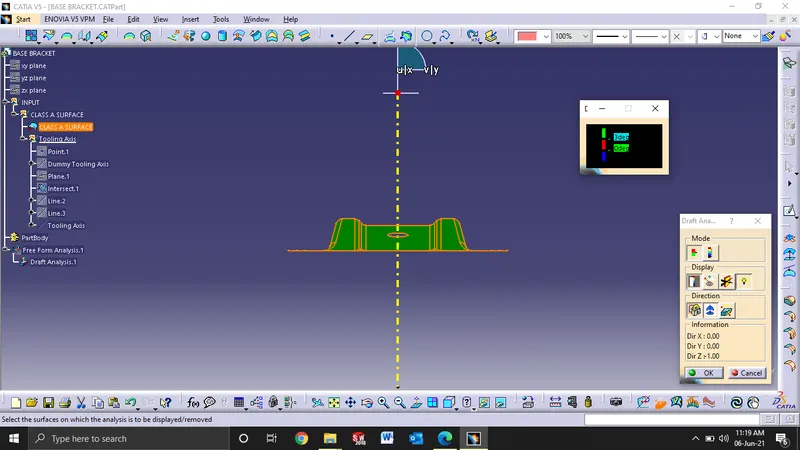
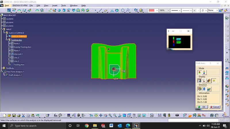
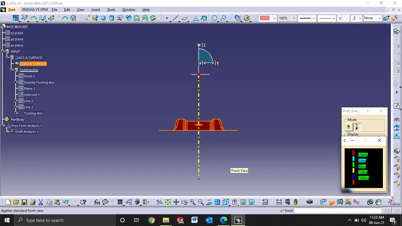
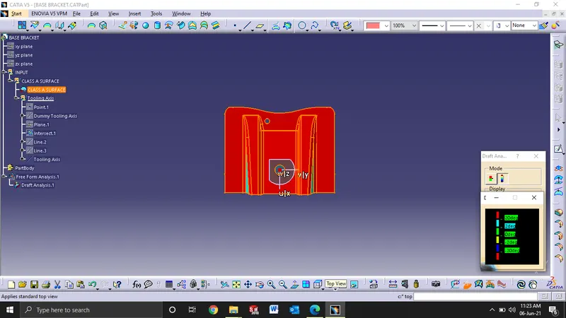
After selection of the material command, we proceed to draft analysis of the Class A Surface.
We select the quick colour codes and then lock the surface in its poisiton.
Then we drag and place the compass on the tooling axis to perform our draft analysis.
The draft analysis of the Class C Solid Surface is done with the same above process. It shows the different colour coding for drafting an element.
Tooling Axis Creation
We first take a point on the base hole and put a line through it.
This becomes our Dummy Tooling Axis.
Keeping the axis as a visual reference we proceed.
Now a point is taken on the hole on the top slant surface.
We take a refence plane on that point with reference to XY Plane.
We intersect our class A surface with the plane to get an intersecting sketch.
On that sketch we draw two lines taking the angular points on the tilted lines.
Then we use the bisecting method to bisect the two tilted lines we created and obtain a straight line which passes from the middle point of the hole.
This line so created is our tooling axis which is further used for draft analysis, sweep in creating the class C surface.