Week 8 Challenge
AIM:- To calculate the centrifugal load and apply the centrifugal load in the stadd pro to calculate the results.
CALCULATION:-
Given:- Design speed = 75 km/h
Radius of curvature = 3 m
Live load, W = 70 KN
Centrifugal force, = (WV2)/127R
= 70*75*75/127*3
= 1033.46 KN
The centrifugal force is 1033.46 KN
The centrifugal force of 1033.46 KN is applied on the superstructure as shown below
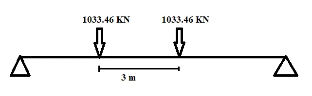
3.6 m is the width of vehicle
PROCEDURE:-
1. Firstly a node is created. The height of pier is taken as 10 m.
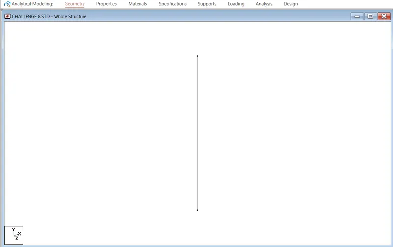
Figure Pier is created using node
2. After that with the help of translational repeat the frame of bridge is created.
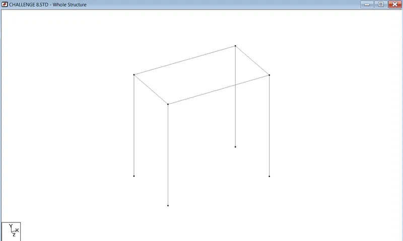
Figure Bridge frame is created with the help of node using translational repeat option
3. The bridge deck is created by using the mesh size of 0.5*0.5 m. The thickness of deck slab is 250 mm
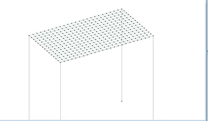
Figure Bridge deck using mesh size of 0.5*0.5 m
4. A circular pier of diameter 2.5 m is created.
5. A fixed support is created at the base of the pier.
6. Tappered I section girder is created using define option.
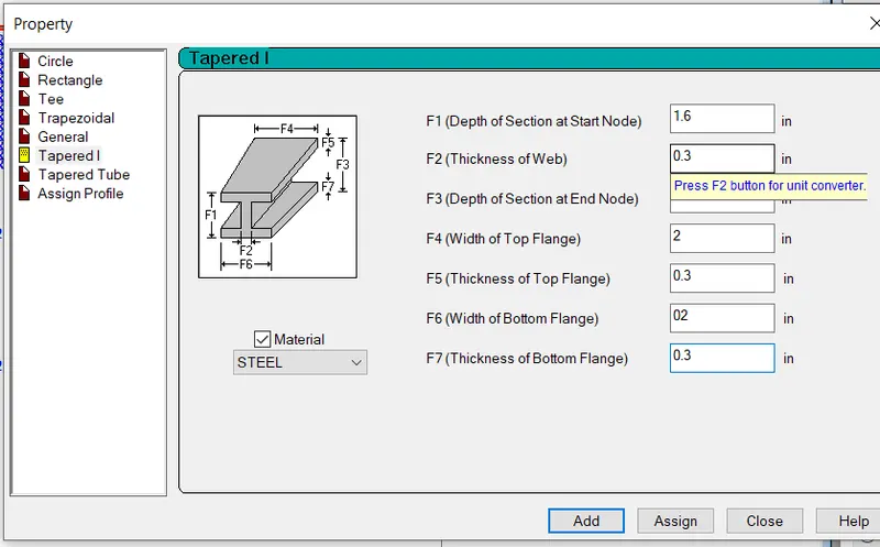
Figure Property of I Section
7. Cross beam of size 0.5 m * 1 m is created.
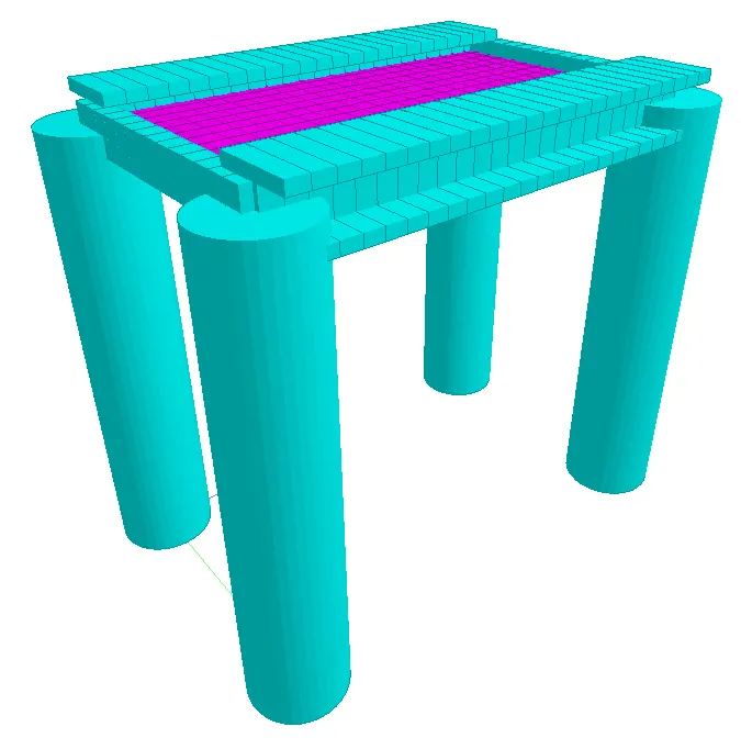
Figure 3D view of bridge
- LOADING
The centrifugal force is applied along the with the axial load i.e. defining it as wheel load.
DEFINITION-------VEHICLE DEFINITIONS-------ADD--------Define load------ADD------LOAD CASE------LOAD GENERATION----
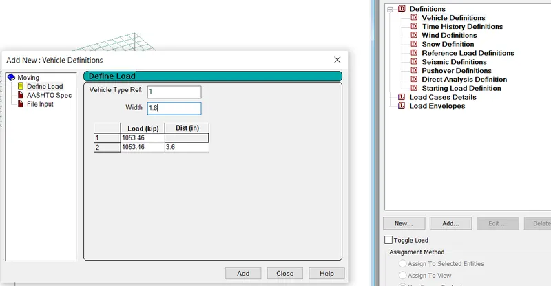
Figure applied load
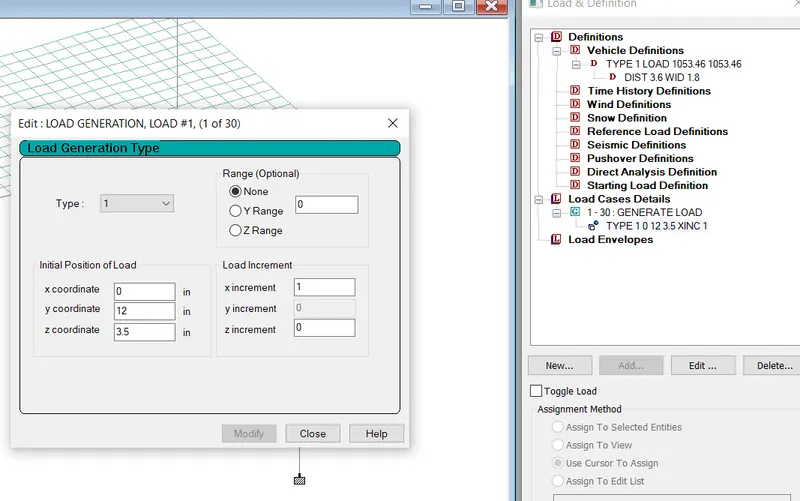
Figure Generated load
RESULT ANALYSIS:-
1. STATIC CHECK:- As the difference between load and reaction is zero, So static check is ok.
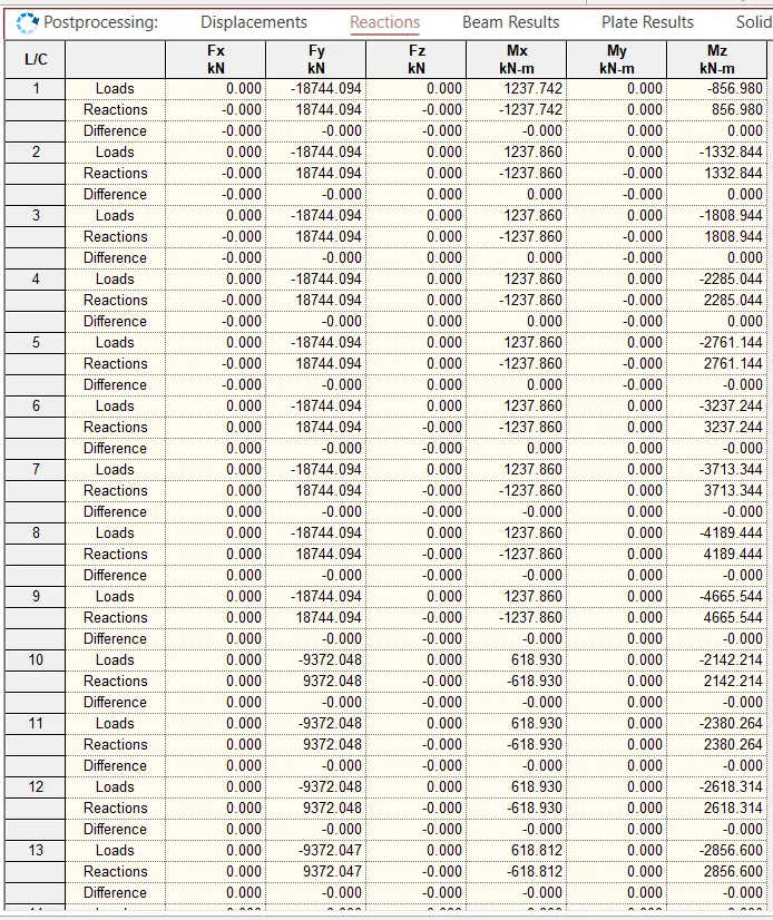
Figure :- Static check
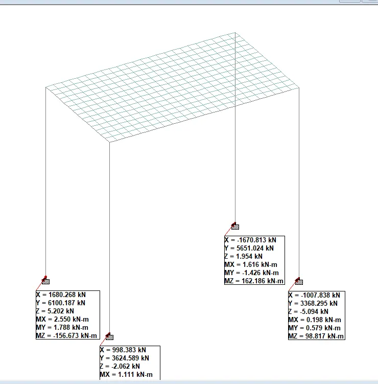
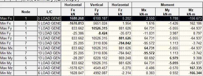
2. REACTION:-
Fx = 16280.280 KN Mx = 64.731 kn-m
Fy = 10526.315 KN My = 6.979 kn-m
Fz = 881.626 KN Mz = 167.355 kn-m
3. BEAM RESULT:- GIRDER
Mz = -279.821 kn-m (At midddle section of beam, Mz = 349.789 kn-m (At support)
My = 6.765 kn-m
Fy = 9193 kn
Fz = 270.199 kn
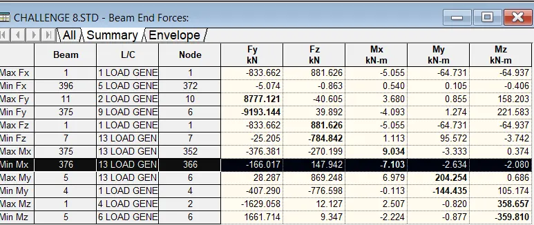
Figure Beam end forces
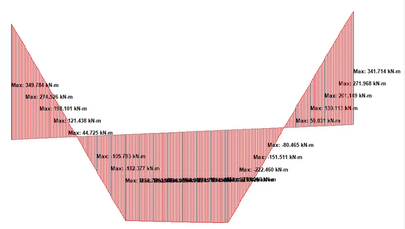
Figure Bending moment diagram of girder
CROSS BEAM
Mz = 193.833 kn-m (At support) Mz = -123 kn-m (At mid of the section)
My = 1.460 kn-m
Fy = 5863.266 kn
Fz = 109.818 kn
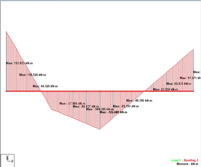
Figure Bending moment diagram of cross beam
4. PLATE STRESSES
Mx = 104.415 kn-m/m
My = 164.358 kn-m/m
SQx = 7117 N/mm2
SQy = 5633 N/mm2
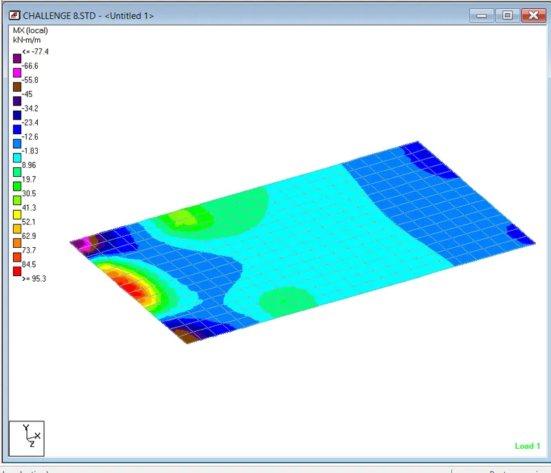
Figure Plate stresses
5. PIER RESULT:-
Mz = 189.163 kn-m
My = 203.189 kn-m
Fz = 881.626 kn
Fy = 833.662 kn
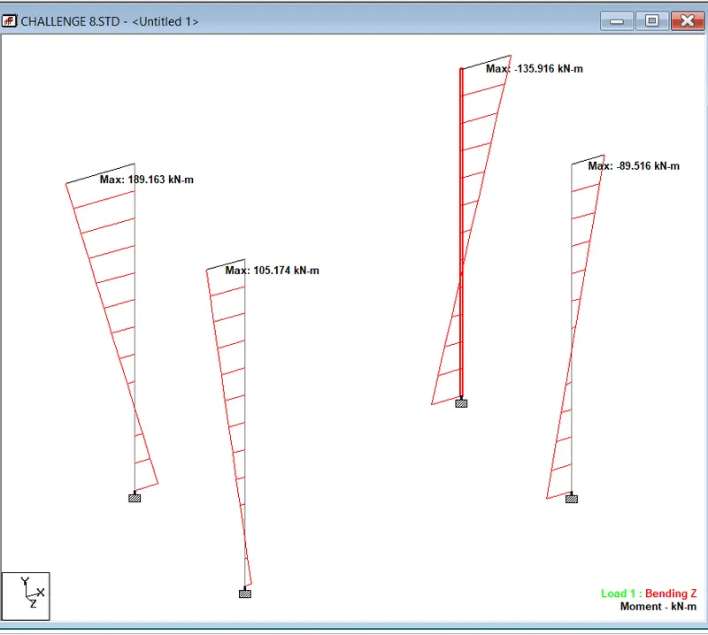
Figure maximum bending moment in column