Week 6 Challenge
INTRODUCTION:- This challenge is focusse on how to apply the utility load on the bridges using the stadd pro software. This study will provide the step by step procedure of designing the deck slab, girder, bottom cord bracing and top chord member.
LIVE LOAD CALCULATION:-
Pipe diameter, d = 700 mm and 200 mm
Pipe type = Class K9 DI Pipe
Span, L = 24 m = 24000 mm
- SELF WEIGHT OF DI PIPE
- For 700 mm dia and class K9 weight = 217.19 Kg/m = 2.1719 KN/m
- For 200 mm dia and class K9 weight = 45.28 kg/m = 0.4528
- For 24 m span weight = 24 x (2.1719+0.4528) = 63 KN
- LIVE LOAD IN DI PIPE
- Load due to water in Pipe = Area x unit weight
= 3.14 x (0.7 x 0.7 + 0.2 x 0.2) x 10
= 16.65 KN/m
- TOTAL LOAD ACTING ON BRIDGE
= SELF WEIGHT OF di pIPE + Live load in DI Pipe
= 2.1719+16.65
= 18.8219 KN/m
The load is applied on the bridge superstructure as UDL
PROCEDURE:-
- Step 1 :- Analytical Modelling
- Opened the GEOMETRY option and in this selecting the HOWE type of truss bridges.
- Defining the section properties of the bridges like thickness of deck slab and bottom and top chord menber as well as bracing. And then after defining the section properties of the pier
- Creating mesh side of 0.5 m x 0.5 m through out the length of the bridges.
- Creating fixed support at the base of pier
- LOADING:- First i apply the self weight of bridge as -1 by selecting the bridge. and then after that live load of 700 mm and 200 mm dia pipe weight is applied on the specified girder.
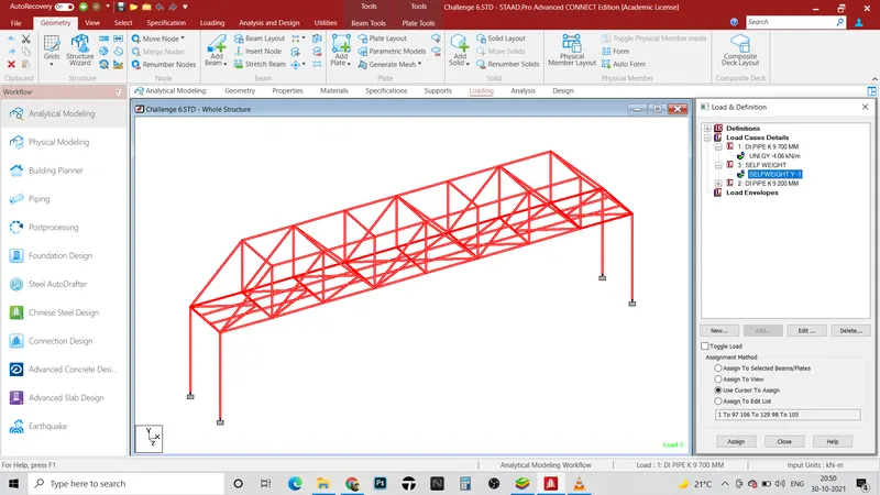
Figure Self weight of bridge
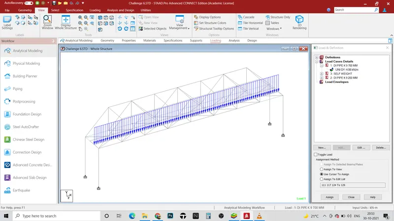
Figure Live Load of 700 mm dia class K9 DI Pipe
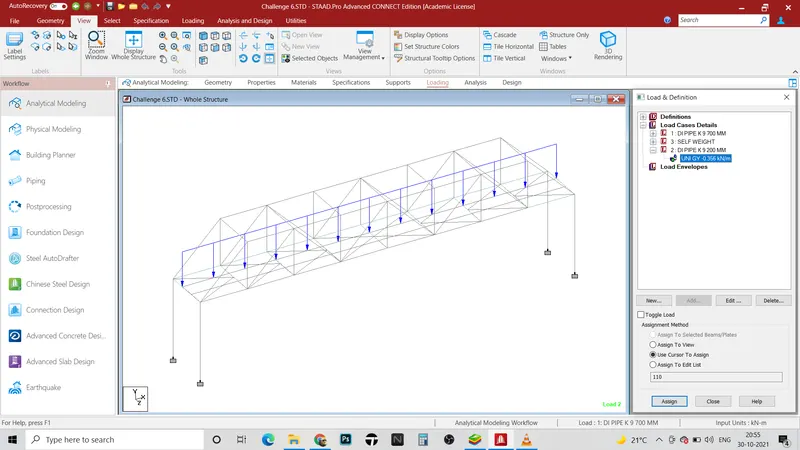
Figure Live Load of 200 mm dia class K9 DI Pipe
STATIC CHECK:- After run analysis first check the static analysis. After checking the static analysis it's ok. The difference between the applied load and the reaction should be zero in static check.
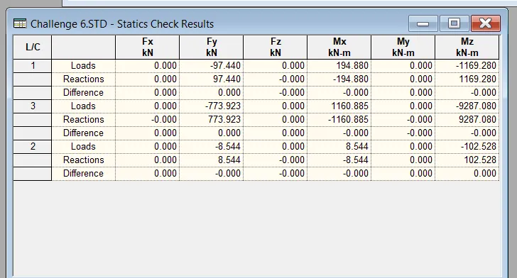
Figure Static Check
REACTION:- Maximum reaction is obtained in case of self weight.
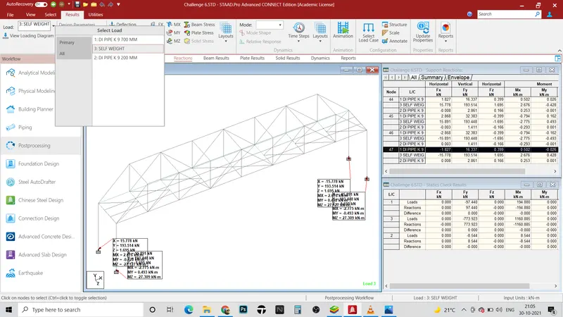
Figure Support Reaction due to self weight
X = 15.778 KN
Y = 193.514 KN
Z = 1.695 KN
Mx = 2.775 KN-m
My = 0.493 KN-m
Mz = 27.309 KN-m
DEFLECTION:- Maximum deflection is 8.681 mm in y direction (Downward) due to self weight
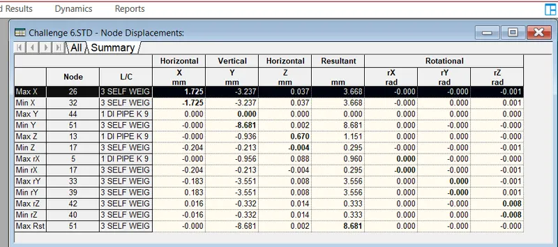
PLATE STRESSES:- Maximum plate stresses is coming from self weight of the structure i.e. Mx (Local)= 6.42603 KN-m/m
Mx (Local) = -2.58498 KN-m/m (Minimum)
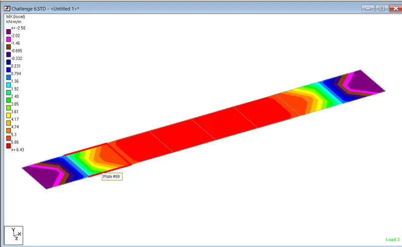 Figure: Maximum Mx local moment
My (Local) = 0.634363 KN-m/m (maximum) and -0.219666 KN-m/m (minimum)
Mxy (Local) = 0.0946898 KN-m/m
SQx = 0.0226168 N/mm2
SQy = 0.0002369 N/mm2
- COLUMN FORCES
Mz = 52.816 KN-m
My = 5.083 KN
Sy = 16.086 KN
Sx = 1.496
- FORCE CALCULATION FOR 700 mm class K9 DI Pipe on Girder
Mz = 5.684 KN-m
My = 0.220 KN-m
Sy = 7.056 KN
Sz = 0.142 KN
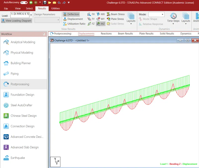
Figure Loading diagram of 700 mm dia DI Pipe
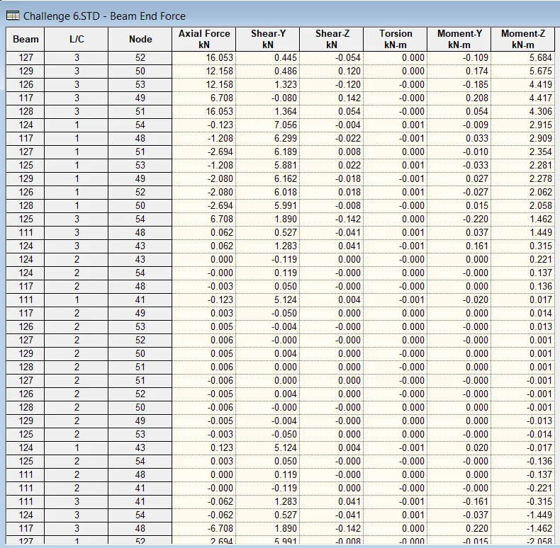
Figure Maximum Mz moment for 700 mm dia DI Pipe
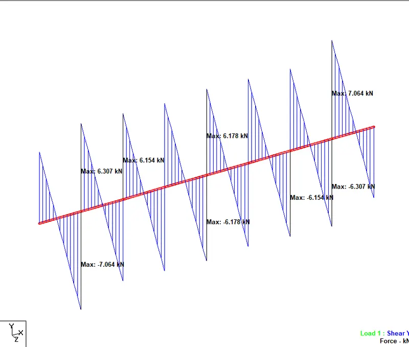
Figure Maximum shear in y direcrtion for 700 mm dia pipe
- FORCE CALCULATION FOR 200 mm dia DI Pipe on girder
Mz = 5.917 KN-m
My = 0.207 KN-m
Sy = 1.799 KN
Sz = 0.135 KN