Week 8 Challenge
Q-1 On the model of challenge-7 ( Pratt Truss) following loading exercise is to be done-
Aim & Introduction-
- A Load case as DL for Dead Load is to be formed
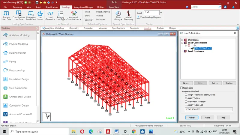
- Self weight on the model/structure is requried to be applied
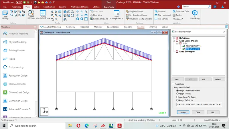
- Member load of 3 kN/m on the rafter is to be applied
- Member load of 6 kN/m on the secondary beams is required to be applied
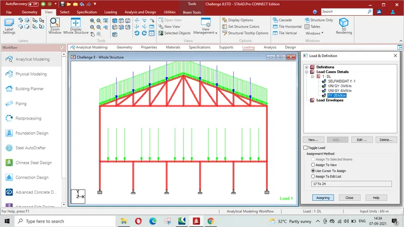
- Point load of 20 kN at node intersecting inclined member on the top chord is to be applied.
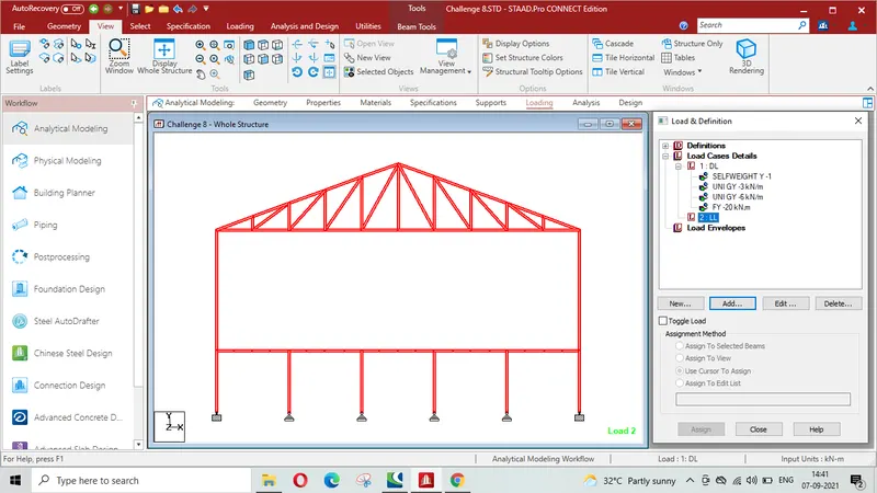
- A Load case as LL for Live Load is required to be formed
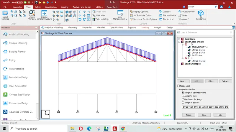
- A Member load of 4 kN/m on the rafter is required to be applied
- A member load of 7.5 kN/m on the secondary beams to be applied
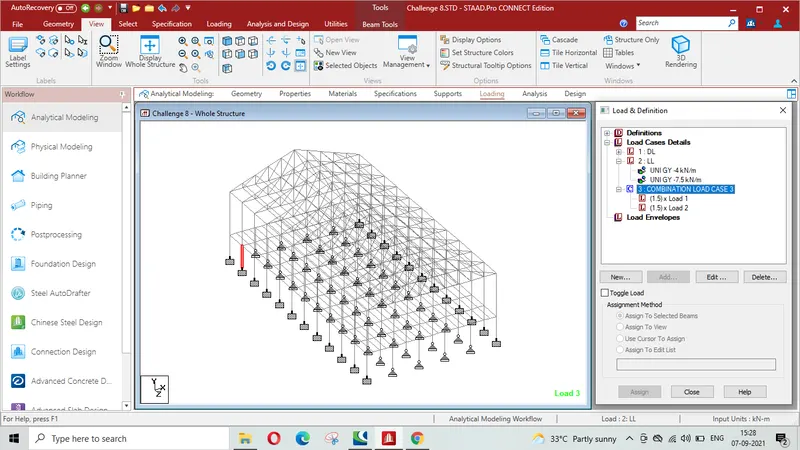
- Load combination 1.5DL+1.5LL is to be formed
Procedure-
Forming dead load as DL
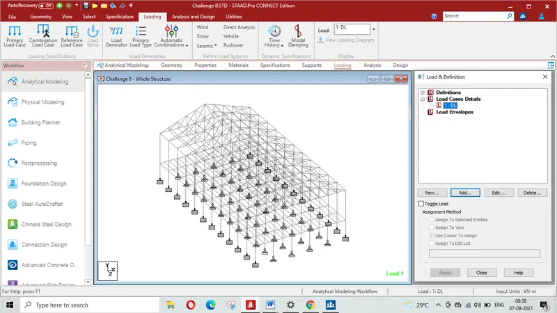
Applying self weight
Applying 3 KN/m on rafter
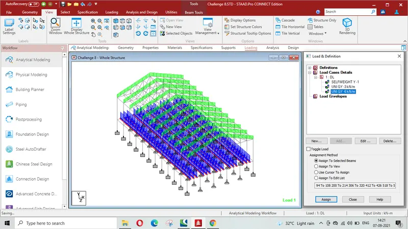
Applying 6KN/m on secondary beams
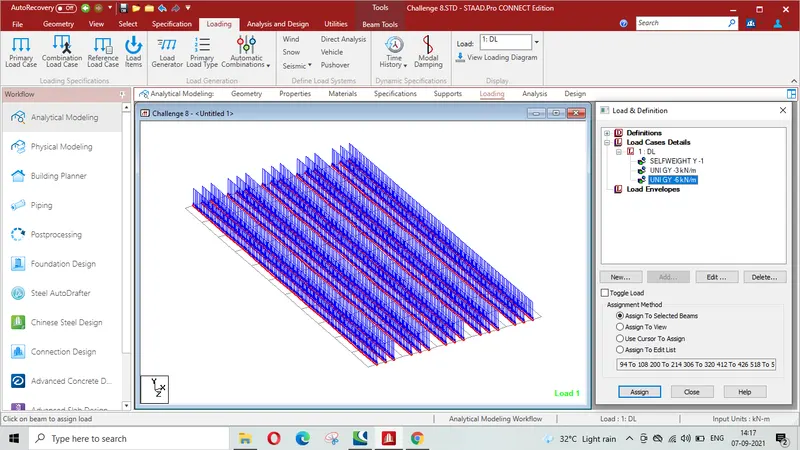
Isometric view showing the member load og 6KN/m on secondary beams
Applyoing point load of 20KN at node intersecting member on top chord
Forming live load case as LL
Applying member load of 4KN/m on rafter
Applying member load of 7.5 KN/m on secondary beams
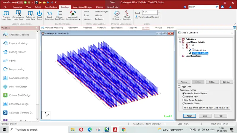
Isometric view showing member load of 7.5 KN/m on secondary beams
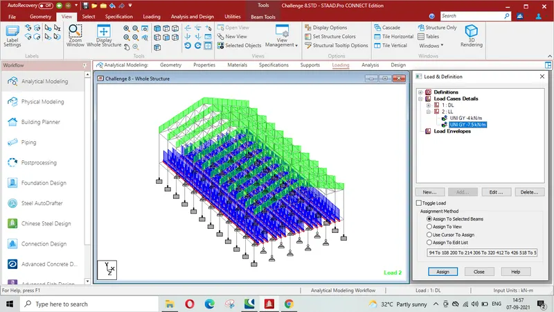
Forming load combination 1.5 DL+ 1.5 LL
STD.Pro model file is attached in which actual loading as per given question can bee seen.
Result-
Thus it is concluded that loading as per the question viz. Dead load ( Nodal load, member load ,. Live load ( member load ) and load combination of DL+ LL has been applied on the model.
Q-2
Aim & Introduction-
To find the maximum force and minimum force for members and to presenr STAAD result.
Procedure-
i)
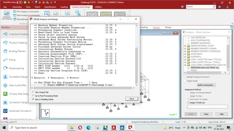
Snap shot/Print screen of Run analysis with 0 error and 0 warnings
ii)
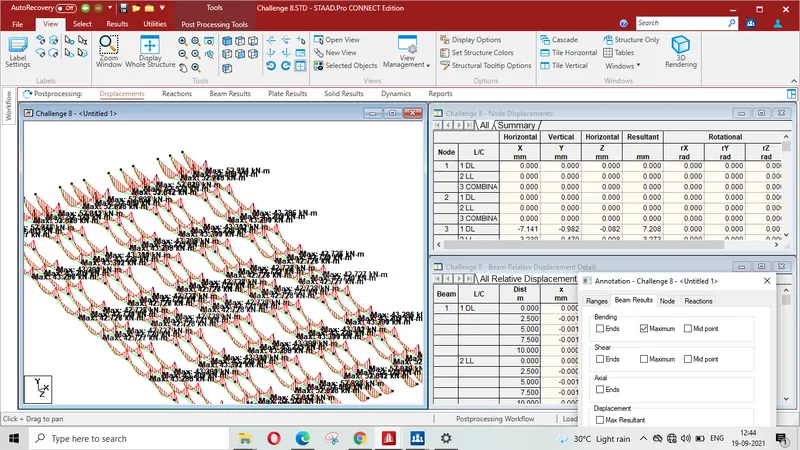
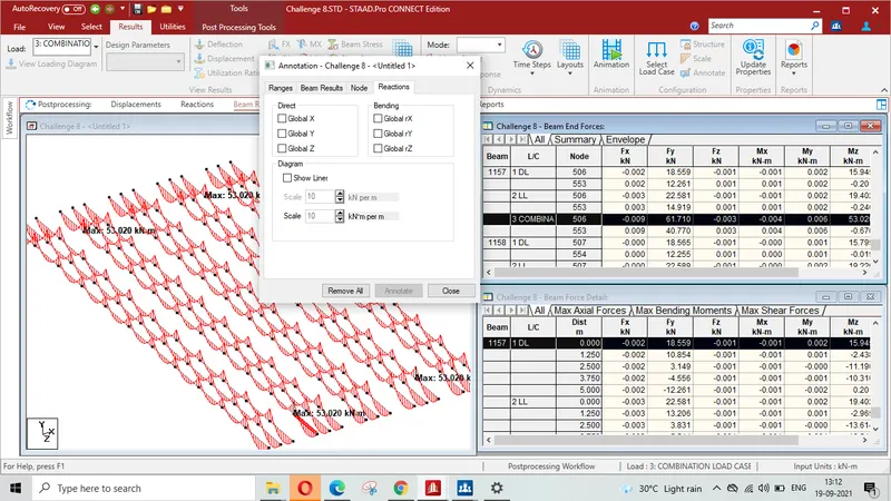
Max moment in the secondory Beam for 1.5 DL+1.5 LL case is +53.02 KN-M on beams Nos 1157 & 1165 and -53.02 KN-M on beams Nos 97 & 105 which have been shown in the following screen shots-
iii)
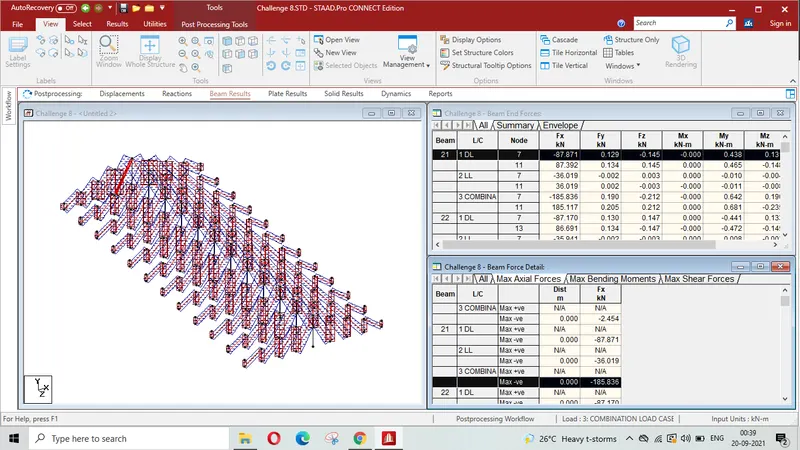
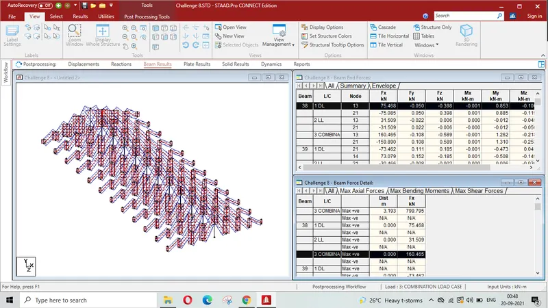
Max axial force on inclined bracing is Fx = -185.836 KN on beam No. 21 and Fx = + 160.465 KN on 38 as shown in the print screens
Member having maximum force for load case of 1.5 DL+ 1.5 LL is beam ( top chord) No. 23 with a value Fx= 803.14 KN asa shown in the print screen below-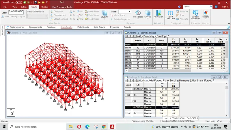
iv)
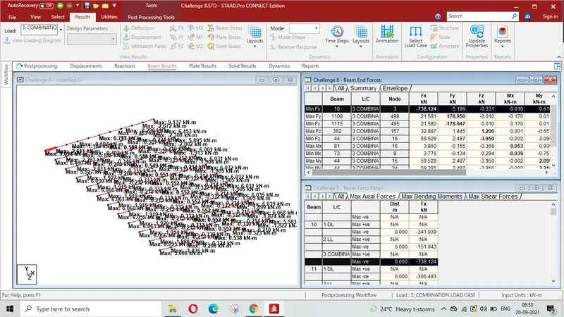
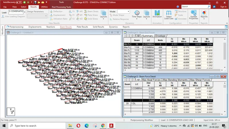
Bottom chord with Maximum Shear Fx is beam No. 10 and Maximum moment Mz is on member No 19
Maximum Shear force Fx= - 738.124 and
Maximum moment Mz = 9.137 KN-M for load case of 1.5DL+1.5 LL
Result- Thus following is concluded-
- Run Analysis command has been performed to the model successfully without any error, warning etc.
- Maximum moment in the secondory Beam is +53.02 KN-M on beams Nos 1157 & 1165 and -53.02 KN-M on beams Nos 97 & 105
-
Max axial force on inclined bracing is Fx = -185.836 KN on beam No. 21 and Fx = + 160.465 KN on 38
-
Bottom chord (beam No. 10) has Maximum Shear Fx= - 738.124 is and Maximum moment Mz (member No 19 ) = 9.137 Q-3
Aim & Introduction- For the attached STAAD file , warnings , instability in the structure are to be identified, fixing the warning & instability then run analysis is to be performed
Procedure-
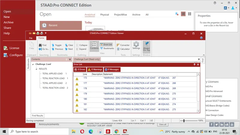
On Run Analysis 8 warnings have been found. Warnings are on account of Zero stiffness at joint 47 & 48 in the direction 3,4,5 & 6 as visible in print screen
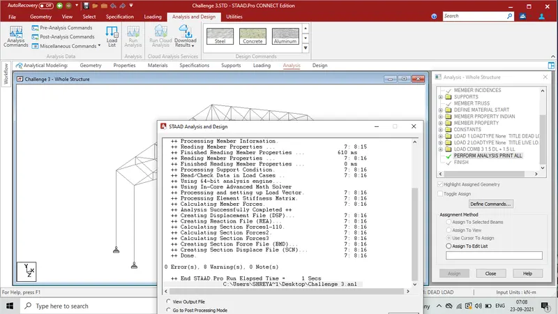
Zero stiffness have been removed which is shown from the Run Analysis Print screen
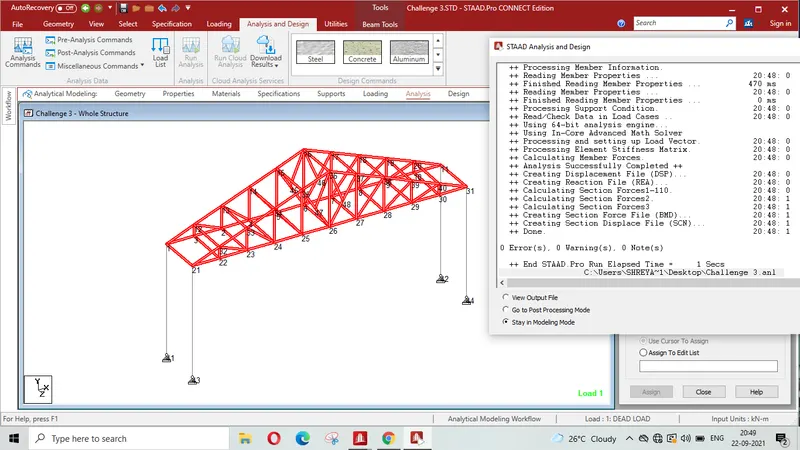
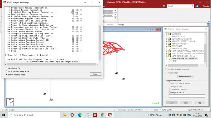
Result- It is concluded that there were 8 warnings in the given model/structure which were observed whille performing the RunAnalysis Command which have been fixed as shown in the attached file of 1.3 KB.
Q-4
Aim & Introduction-
To apply Design parameter for structure modelled f for code IS800:2007.
- Effective Length Lx, Ly, Lz for beams, Truss elements
- Effective length factors Ky, Kz for Columns
- Apply other design parameters for respective members
Procedure-
Effective length Lx, Ly & Lz is assiigned to the trussmembers
Ky & Kz is assigned to column members
Other parameters are also assigned to structure
staad file is attached for above assignment
Result-
It is concluded that all desired design parameters are assigned to the model