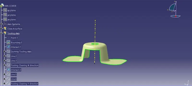
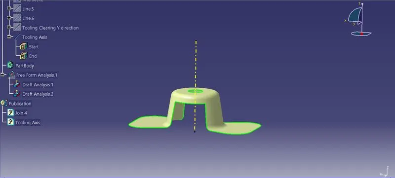
Week 8 - Challenge 1 - Draft Analysis on a Fan Cover
Challenge:
Creating the tooling axis for the given Fan cover model meeting the requirements of the draft angle and performing the Draft analysis for the model.
Step 1:
To create the tooling axis, initially ensuring the boundary of the fan cover model is fully enclosed.
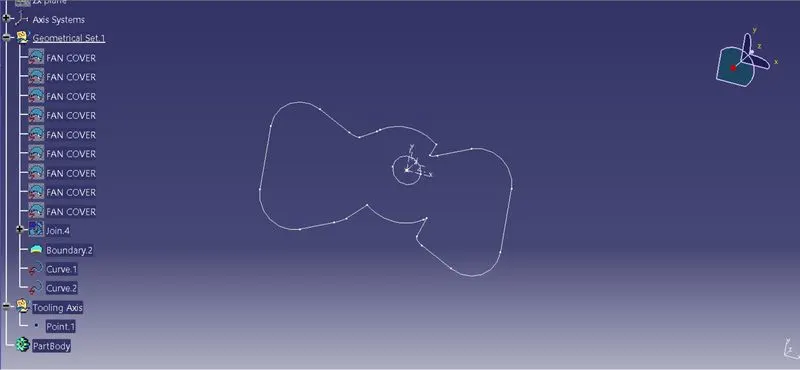
Step 2:
Once we get boundary layer, we split the model to get the tooling axis dircetion from the Z-X direction by intersecting the model at the direction.
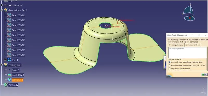
Step 3:
Using the intersection lines of the model, we are gonna create the bisecting line using the existing intersection lines. hence we acheived the tooling axis for Z-X dirction.
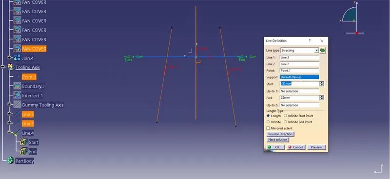
Step 4:
we split the model to get the tooling axis dircetion from the Z-y direction by intersecting the model at the direction.
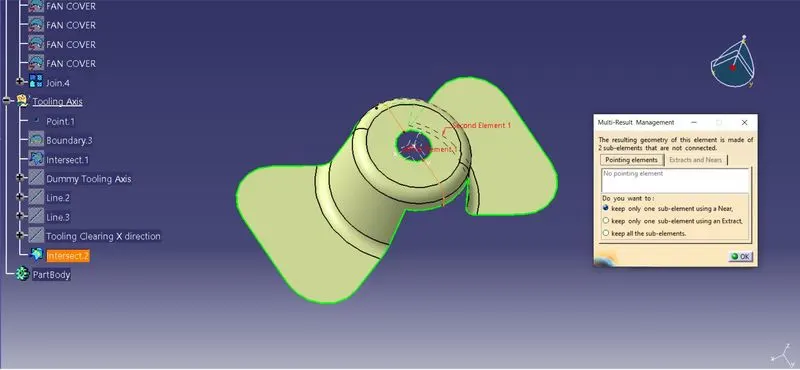
Step 5:
Using the intersection lines of the model, we are gonna create the bisecting line using the existing intersection lines. hence we acheived the tooling axis for Z-Y dirction.
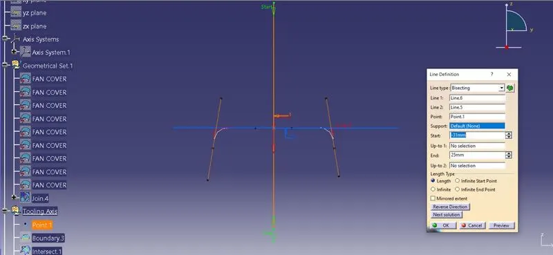
Step 6:
By using the tooling axis of both ZX and ZY. we creating the bisecting lines to get final tooling axis for the fan cover model.
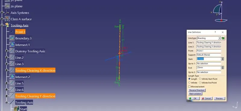
Step 7:
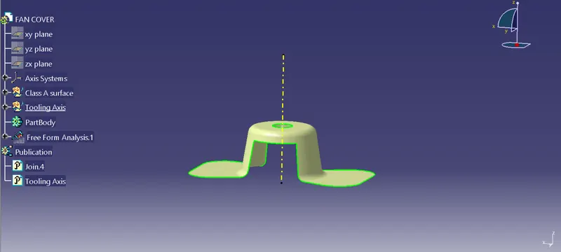
Once we get the final tooling axis , we gonna publish the Class A surface and Tooling Axis as shown in the figure.
Step 8:
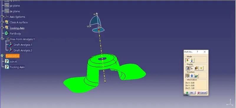
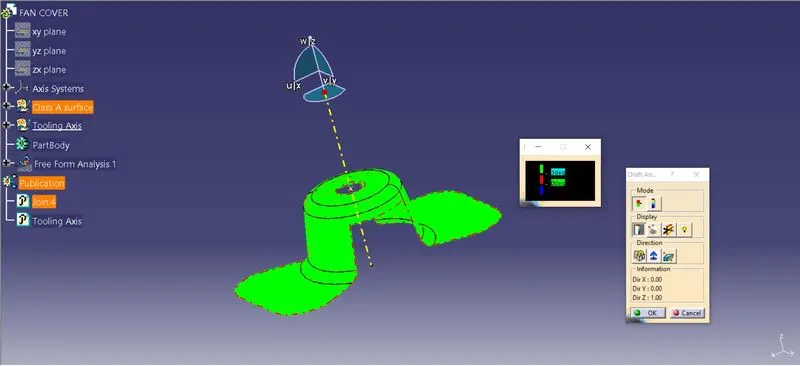
This fan cover model is now ready to draft analysis, before doing it ensure the model is under material proporties . Before starting analysis we gone place gone lock compass to the tooling axis as shown below. it exposes the tooling direction of the model.
Step 9:
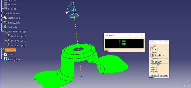
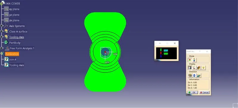
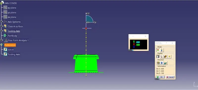
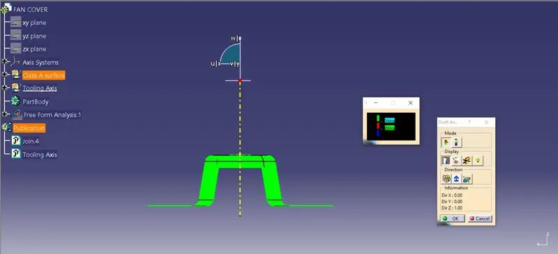
Now we are gonna check the draft analysis of the model by using anlge of 3 degree, which is shown colour code variant dialogue box. it appears green for 3 degree, hence it accepts the draft angle.
Step 10:
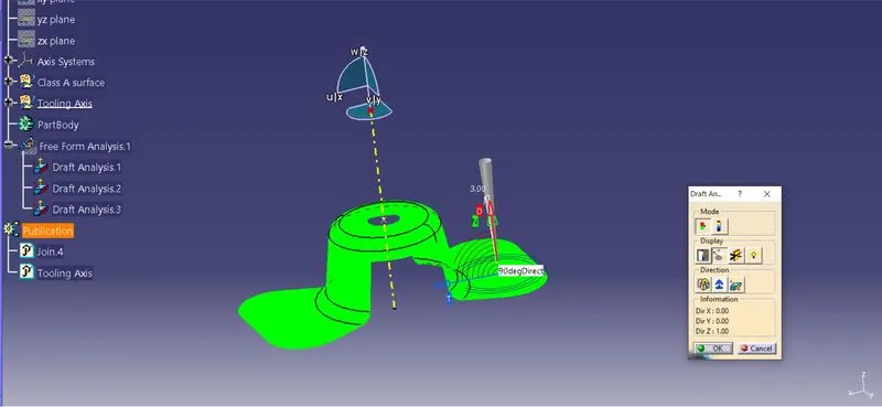
Now we check the draft angle over all the surface of the model, to ensure we had proper angle using draft tool.
Screen shots of the Model:
Isometric view:
Top View:
Front View:
Side View:
Expanded Tree Structure: