Week 8 - Challenge 1 - Draft Analysis on a Fan Cover
Draft analysis of Fan cover
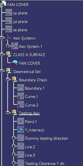
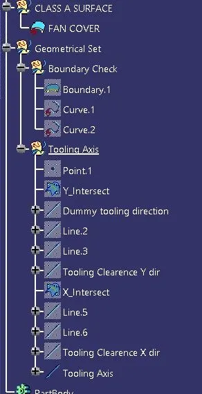
Step 1- Check the received Class A surface for any open surface using either joint command and visual inspection or creating a boundary over the product using boundary feature and check for any broken sketches.
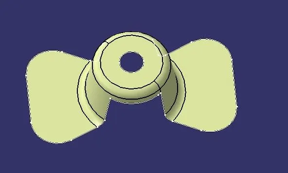

Step 2- Check for possible tooling directions.
X Direction- The problems in this direction is that, the presence of slot in Y direction, presence of hole in Z direction and part need to be manufactued in 2 halves.
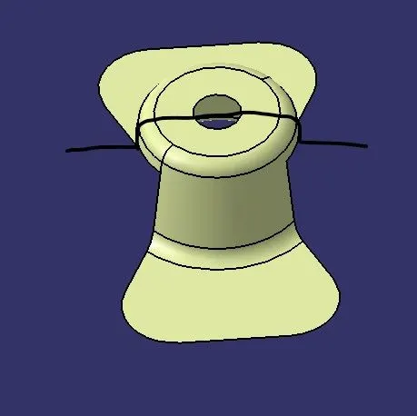
Y Direction- The problem in this direction is the presence of hole in Z direction and the component needs to be manufactured in 2 halves.
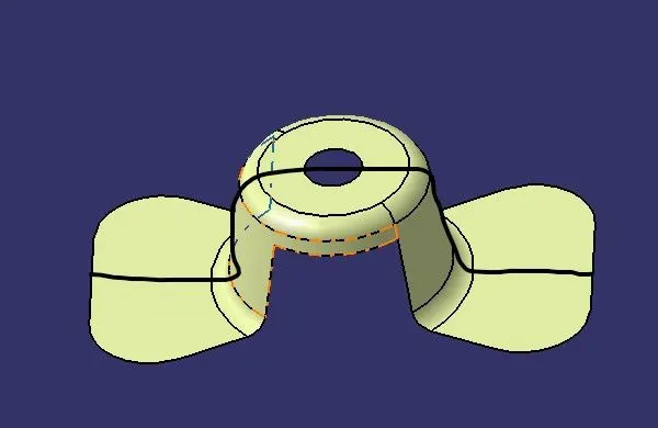
Z Direction- This is the best tooling direction as the hole, slot and the entire component can be manufactured as a single commodity.
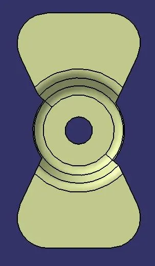
Step 3- Creation of tooling clearence in X and Y direction.
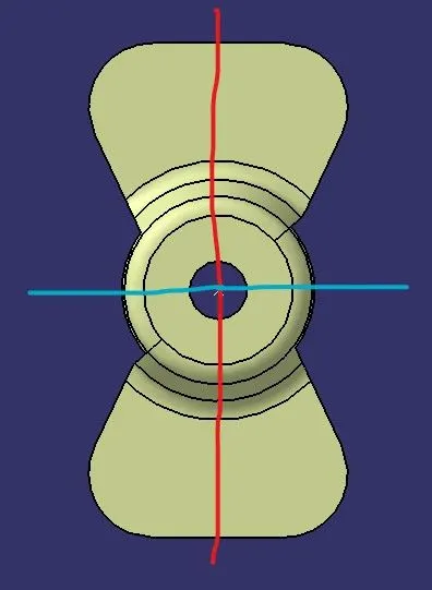
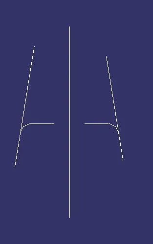
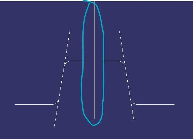
Step 4- Creation of Tooling axis. The bisecting lines formed of X and Y clearence will be the tooling direction.
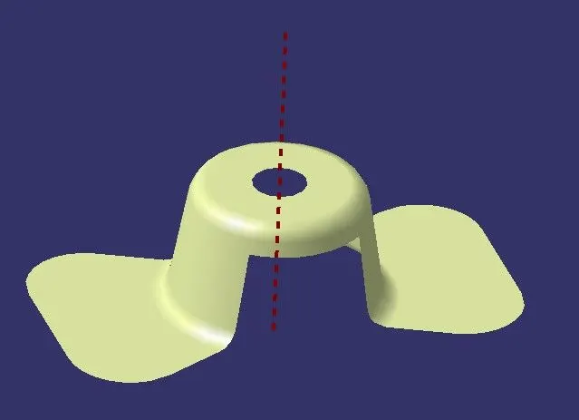
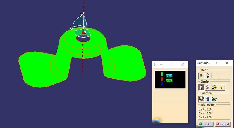
Step 5- Draft analysis.
Draft analysis can be carried out only if the component is in material mode .
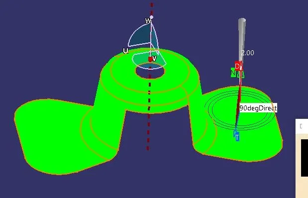
After the draft analysis is activated, drag the compass and place it on the tooling direction and later lock it in that position.
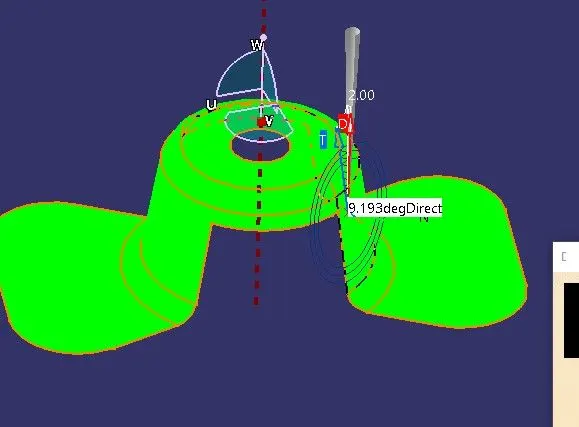
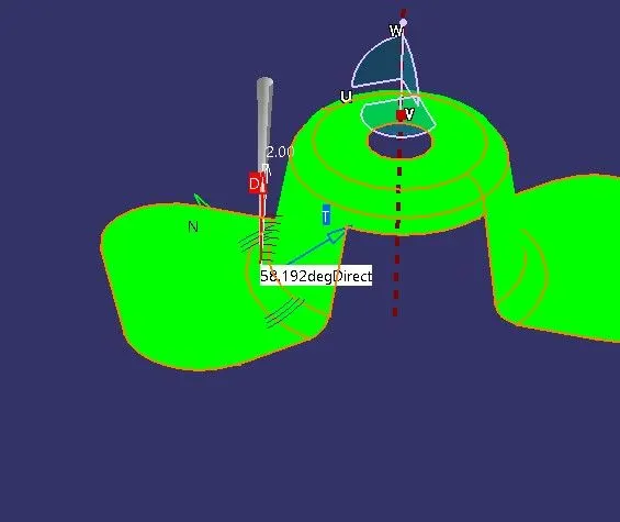
While hovering over the component, it will be highlighted in red, while clicking the component, the draft analysis would give a detailed report, on wether or not the component is manufacturable using the tooling direction.