Week 8 - Challenge 1 - Draft Analysis on a Fan Cover
To check the gap between the surface
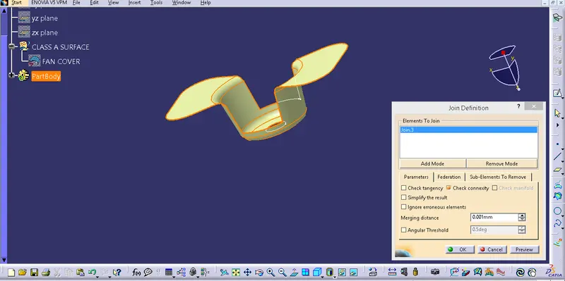
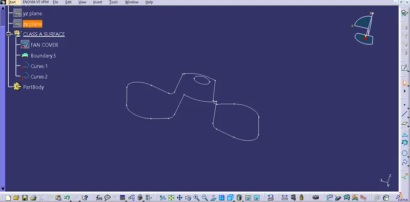
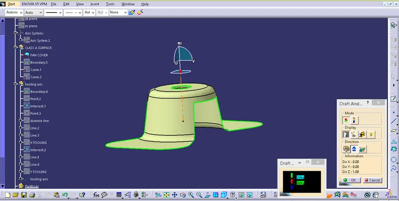
First, check the connectivity of the Class A diagram with the joint definition toolbox to ensure the surface gap between the components. The same function can be done through the boundary option. After disassembling the boundaries, there will be two curves. The two curves represent the inner and outer curves to check the continuity. The above-said procedure is carried out to ensure that the diagram has no gap between the joins.
Tooling axis of the components:
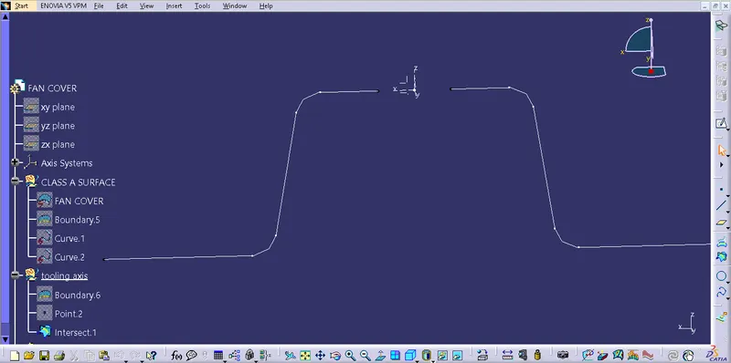
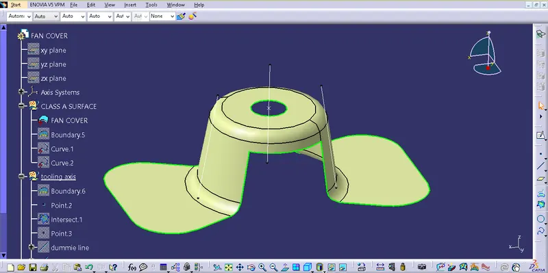
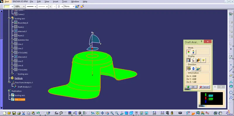
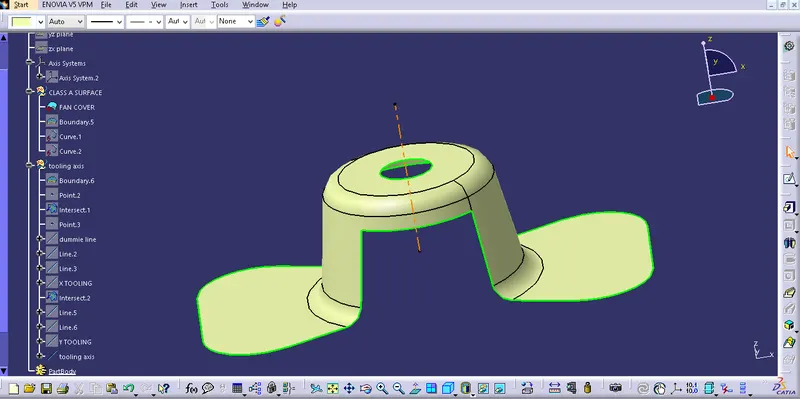
To create a tooling axis initially, geometrical sets were created and the intersecting point was created in the middle of the hole. The intersection line was created for the ZX plane. Based on the inclined line a bisecting line is created. Again tooling axis was created for the ZY plane. With reference to ZX and ZY bisecting line is created and created line is the tooling axis. After that tooling axis and fan cover are published. Fit the compass into the tooling axis and alter the angle based on the colour displayed.