Week 8 - Challenge 1 - Draft Analysis on a Fan Cover
DRAFT ANALYSIS:
A small draft angle is provided to each area of the components in order to get an easy removal of thr component from the tool.
Generallly we do the draft analysis in the cad software(CATIA , NX etc.) and this technique is used to analyze whether our model is manudacturable based on the draft condition applied.
Here we provide a direction in which the componenet should eject from the tool inorder to get an easy removal of component.
Report on Draft analysis in CATIA for the given component(Fan cover).
Step 1:
Check the continuity of the components by using Join command
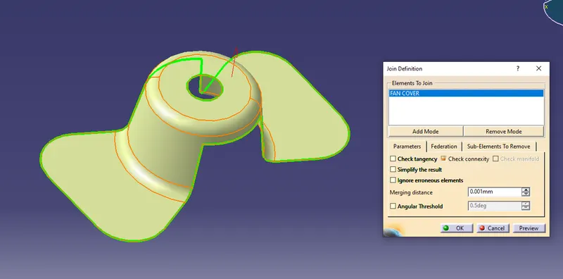
or
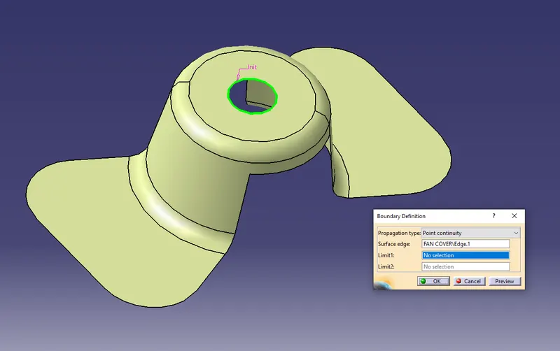
use boundary command and extract the bounday of the component, if no discontinuity in the boundary which is extracted then the surface & curvature continuty is OK for the component.
Step 2:
Change the view mode to customize view parameters and select material option from the mesh
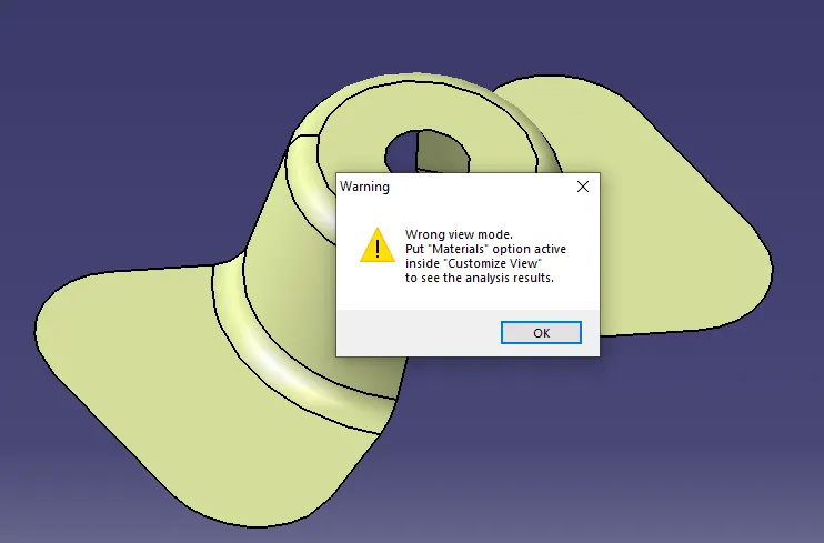
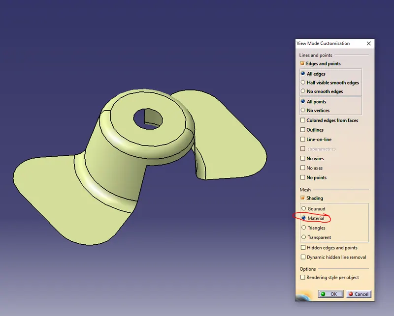
Step 3:
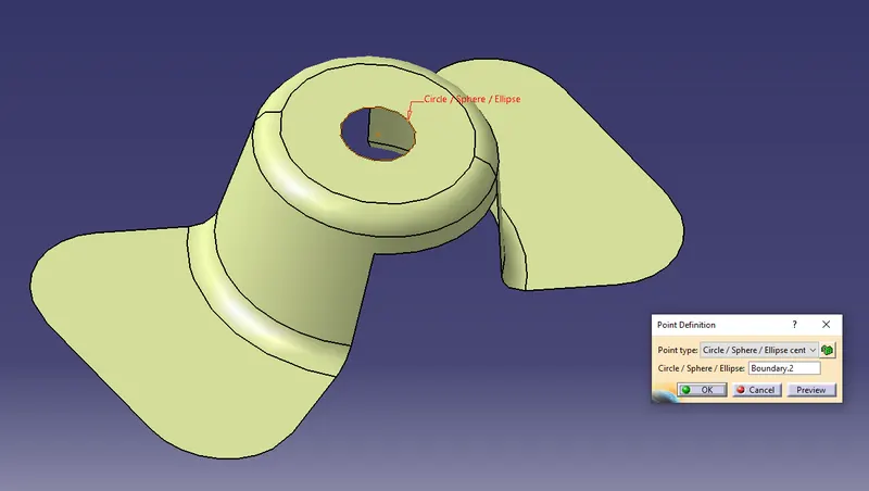
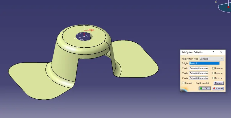
Now extract a boundary for the top circular profile and then create a point through the center of the circular profile & also create the axis
Step 4:
Create a random line from the point using point & direction option line command.
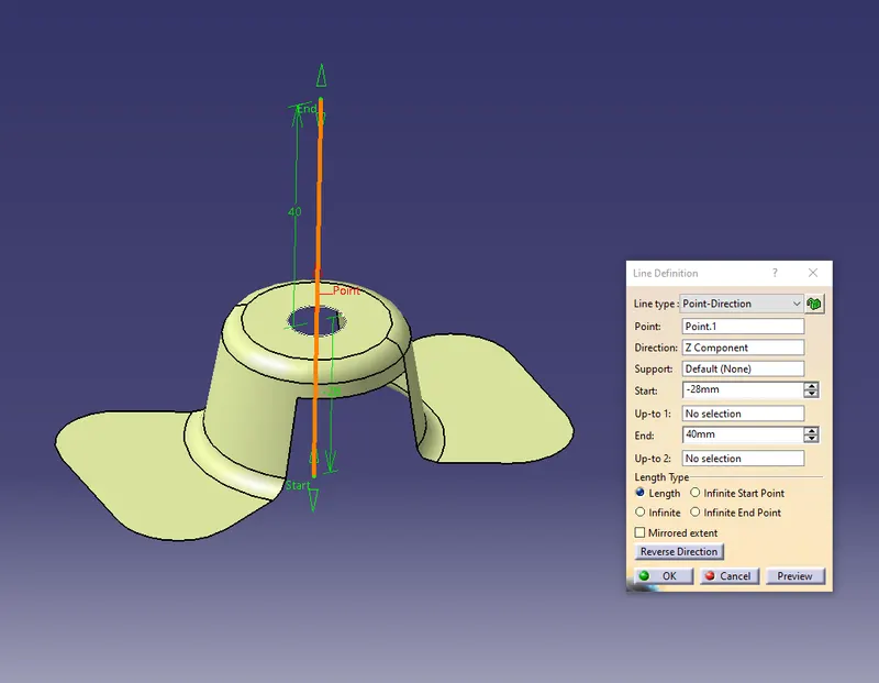
Step 5:
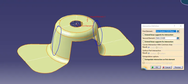
Create the tooling axis in X direction by bisecting the lines from the intersection od the XY plane & component.
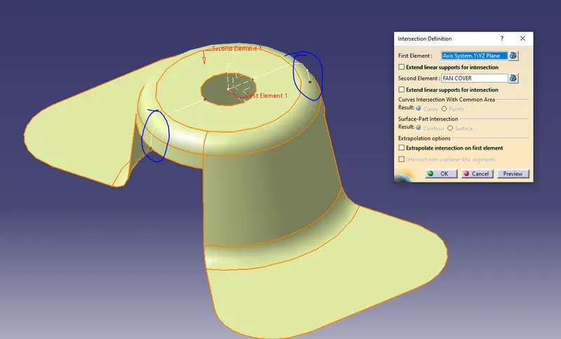
similarrly Create the tooling axis in Y direction by bisecting the lines from the intersection od the YZ plane & component.
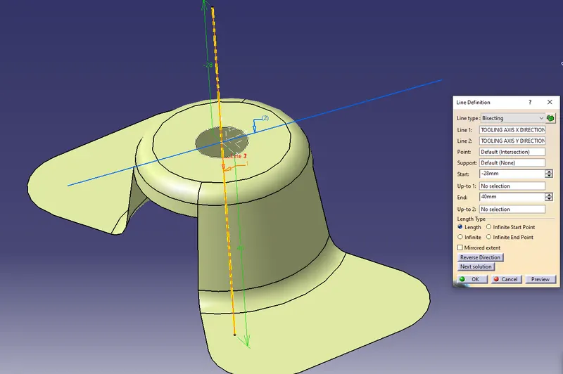
Now create the main tooling axis by bisecting the TOOLING AXIS X DIRECTION & TOOLING AXIS Y DIRECTION.
Step 6:
Draft analysys option is available for the following workbenches:
- Part Design
- Generative Shape Design
- Wireframe
- Freestle shaper
Location is as below
Insert > Analysis > Feature Draft analysis
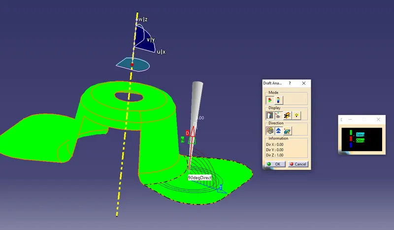
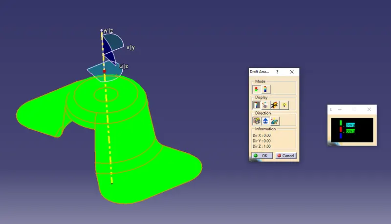
Draft anaysis dialog box with colour scale(with quick analysis mode) appears on the screen. So the first mode option is the quick analysis mode and second is full analysis mode.Here the quick analysis mode is used.
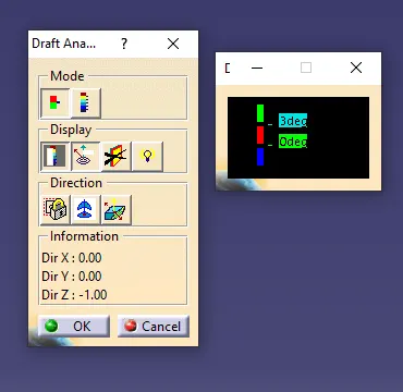
Change the value of the green according to the draft angle provide to the part. Here for the fan cove, the ideal draft angle is 3 deg.
Step 7:
Drag the compass and place it over to the MAIN TOOLING DIRECTION.
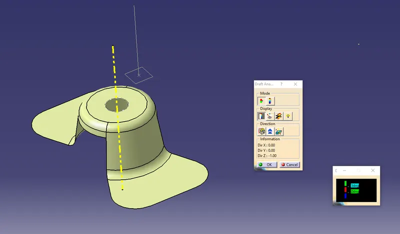
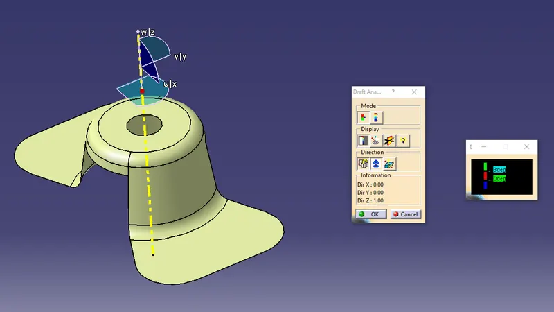
Now press the lock symbol as shown in the below
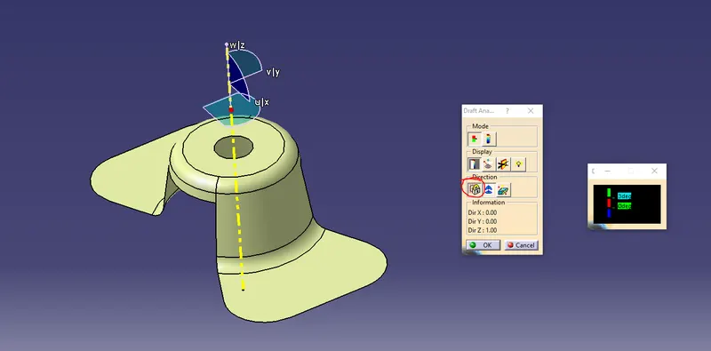
Click on the components
Conclusion:
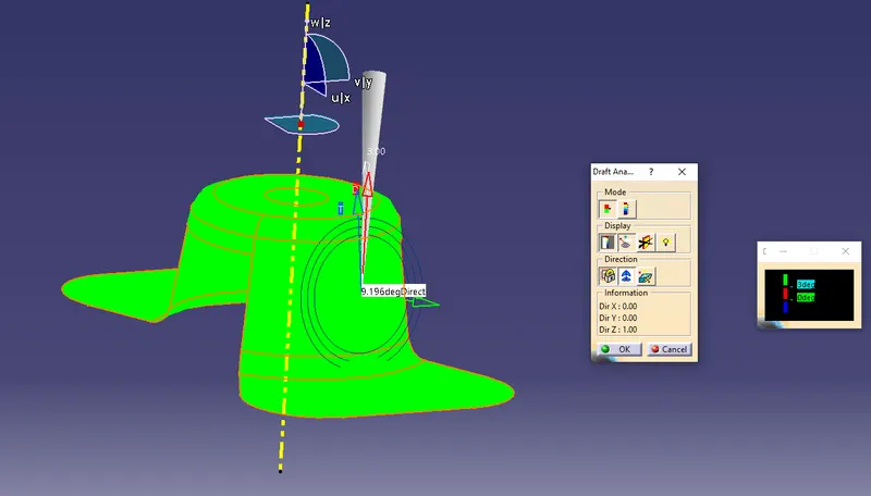
The green colour of the component show that the part clears the tooling direction and can be manufacturable.
Analysis under the Running point:
This option is used to highlighted the exact draft angle of the face.For the we need to move the point along the faces.