Week 8 - Challenge 3 - Switch Bezel Design
1.DRAFT ANALYSIS FOR CLASS A SURFACE
Step 1: Check for any discontinuities in the surface
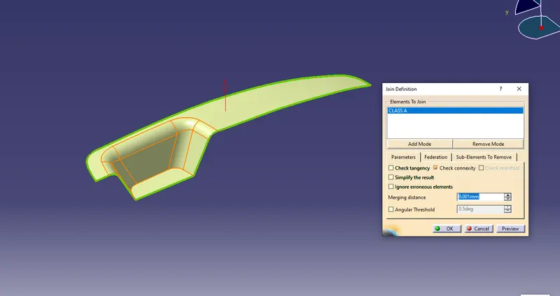
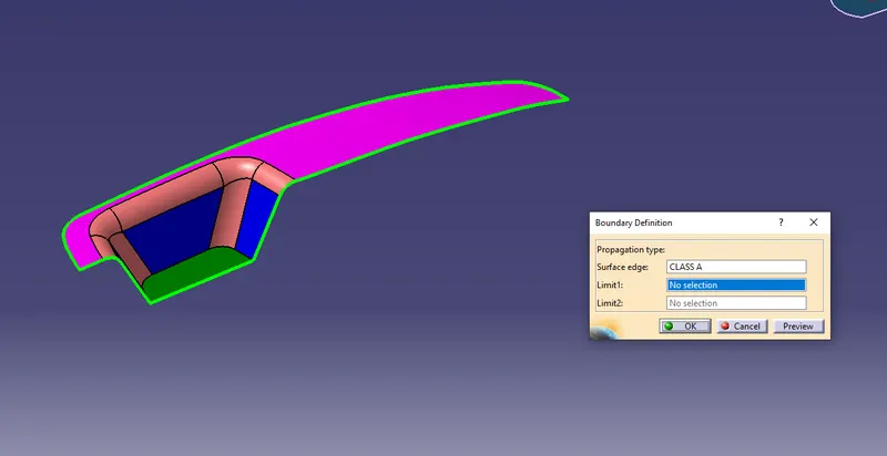
Check the Surface continuity of the given input surface(To confirm whether any discontinuity or patches)--> We can confirm it by using join command or boundary command Generative surface design
Below screenshot shows the Join Command
Below screenshot shows the Boundary command.
Step 2: Dummy Tooling Axis creation
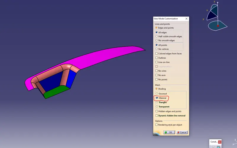
Change the view mode to customize view parameter and select material option from the mesh
Create the point on the bottom surface
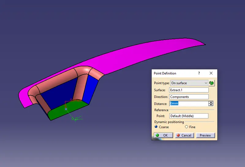
Craete the Axis system at the point created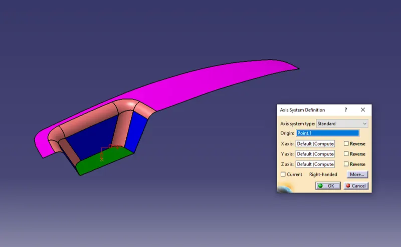
Step 3: Main Tooling Axis creation using Bisecting method
Take an intersection between ZY plane & the input surface
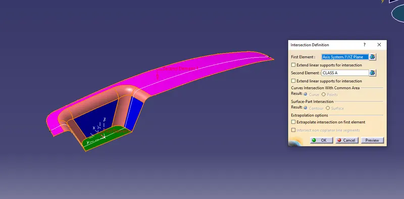
create the lines for the surface which we need to confirm the draft angle(whether it clears the tooling direction or not)
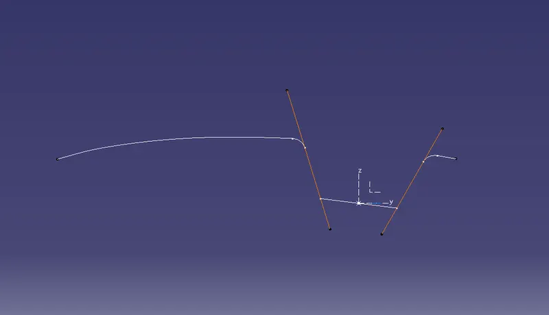
Now create the Tooling axis in Y direction by bisection the two lines
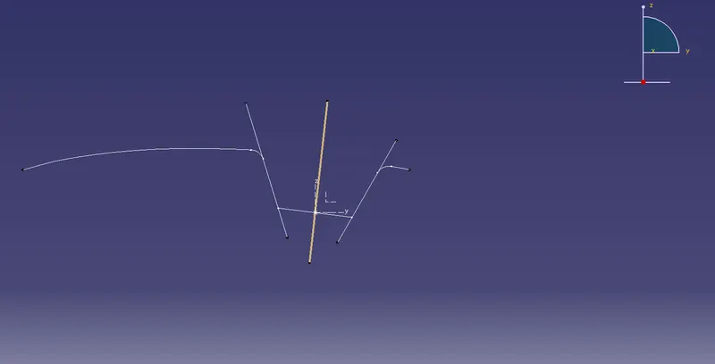
Similarly take intersection between XZ plane & Class A surface
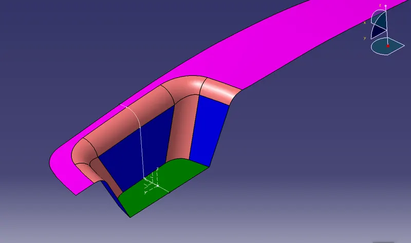
create the lines for the surface which we need to confirm the draft angle(whether it clears the tooling direction or not), from the reference of intersection lines
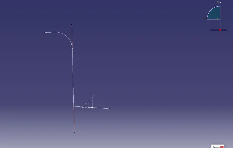
Draw a Tooling Axis X Directionn at angle of 6deg approximately withe line created above
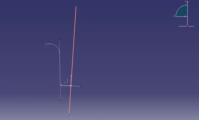
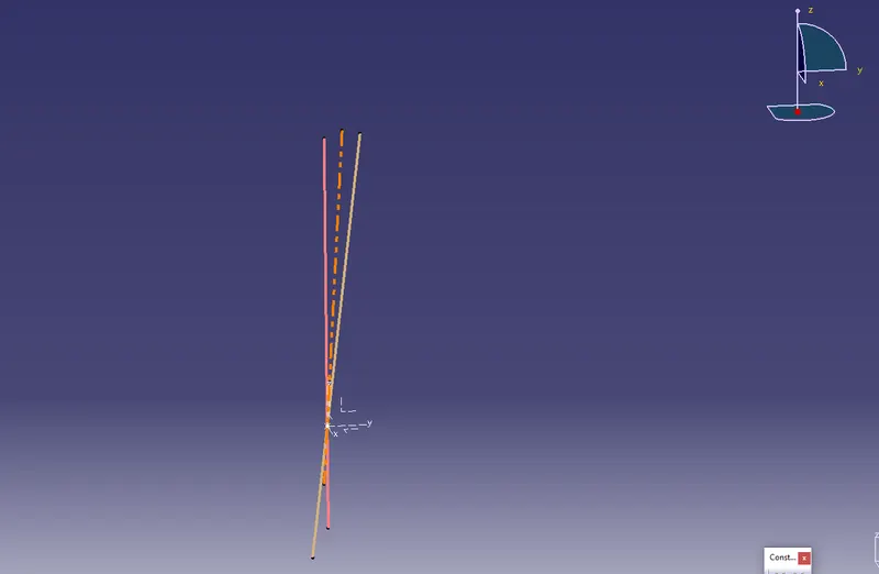
Now create MAIN TOOLING AXIS by Bisection the the Tooling axis in X & Y Directions
Step 4: Draft Analysis
Insert --> Analysis--> Feature draft analysis
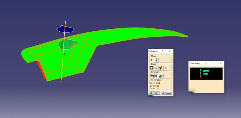
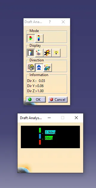
Draft analysis with color scale(with quick analysis mode) appears on the screen. So the first mode option is the quick analysis mode and second is fully analysis mode. Her the quick analysis mode is used.
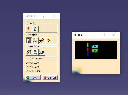
Change the value of green according to the draft angle provided to the part. Ideal draft angke is 2.9deg or 3 deg.
Drag the compass and place it over to the tooling axis.
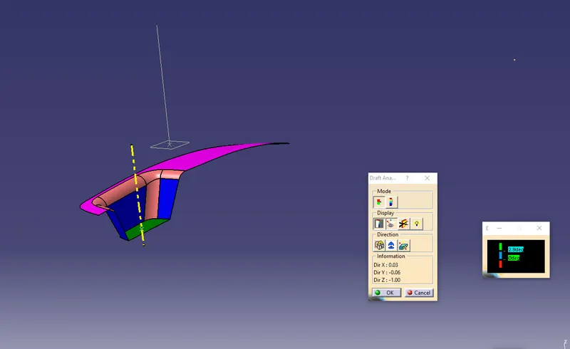
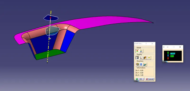
After placing it, click anywhere on the part
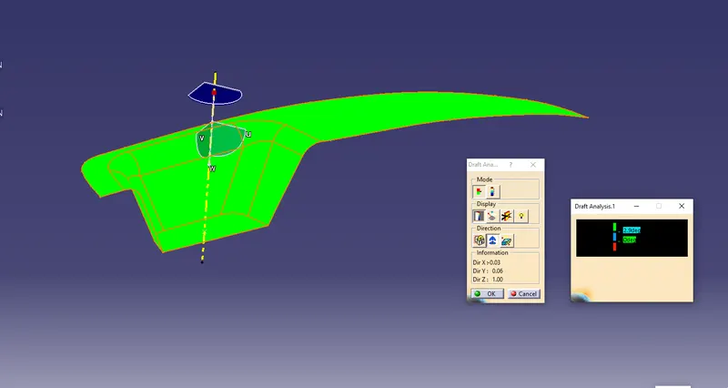
DRAFT ANALYSIS FOR FINAL PLASTIC COMPONENT
Insert --> Analysis--> Feature draft analysis
Draft analysis with color scale(with quick analysis mode) appears on the screen. So the first mode option is the quick analysis mode and second is fully analysis mode. Her the quick analysis mode is used.
Drag the compass and place it over to the tooling axis.
After placing it, click anywhere on the part
Refer the below image for it
Color scale variant
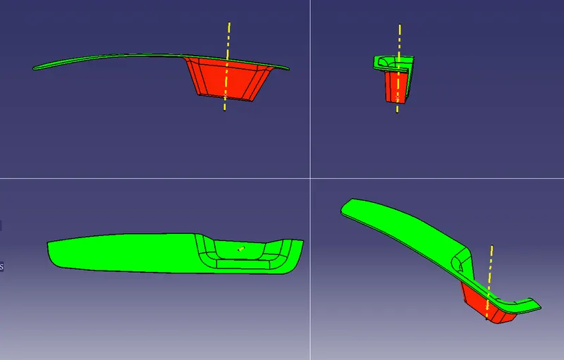
Below Screenshot is for solid model with the proper color code of the draft angle in various orientations (Isometric, Front, Side, and Top View)
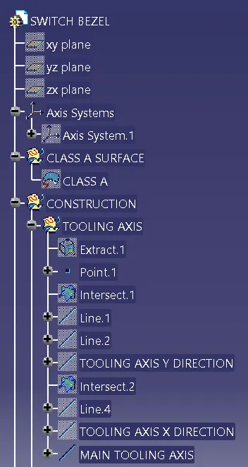
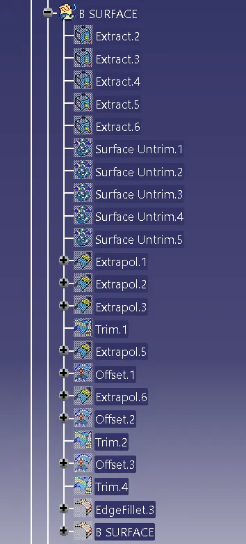
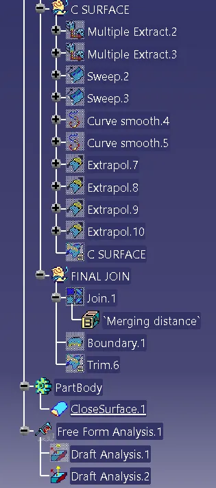
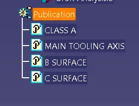
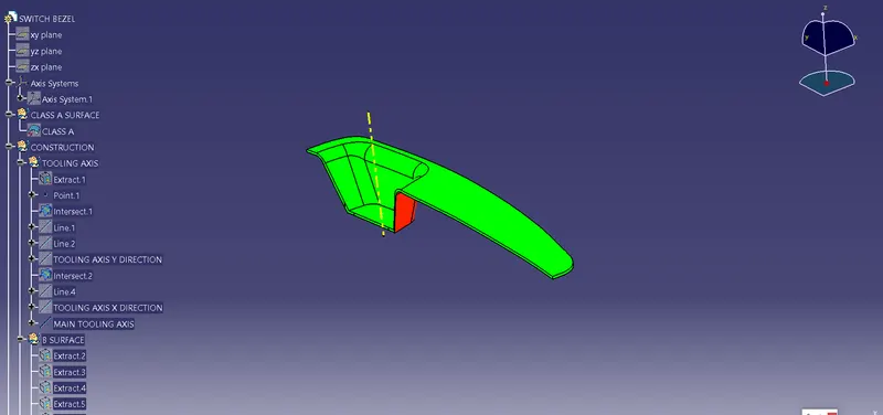
The complete tree structure for the components is as below(includes Class A,B, C Surfaces & Main Tooling Direction & also Draft analysis for class A surfcae & final plastic component)
Extract the surface