Week 8 - Challenge 1 - Draft Analysis on a Fan Cover
Aim:
- Create the tooling axis for the given Fan cover model meeting the requirements of the draft angle and perform the Draft analysis on the model.
Background:
Draft is an angular tapering provided at design stage to plastic component to be manufacturing using injection molding technique. Draft allows for parts to release from the mold.
Draft is required on all parts in the direction of mold release. Plastic components have a tendency to shrink and attach to the core of the mold while cooling hence causing friction on the walls of the component itself. This may lead to rough finish of the part and even damage the mold. Hence draft is necessary.
Most of the parts require minimum of 1/2 or 1 degree of draft angles, however 3 degree is widely accepted as the norm. Surfaces like instrument panels are given even 7 degree draft angles. Screw bosses,ribs and stiffners are provided with minimum possible draft angles.
Tooling axis:
The direction in which the mold opens or closes is called the tooling axis. Draft is given along this axis.
Draft Analysis:
It is an analysis tool in CATIA which identifies the critical area in a component on which the draft is provided such that the draft angle is optimum for injection molding.
It is the first step done by the plastic design engineer after receiving a class A surface . When the draft analysis is successful class A is converted into NPD CAD.
Procedure:
Step 1:
Check class A surface for any discontinuity. It can be done using join or boundary tool in CATIA which helps in identifying any discontinuity.
Step 2: Tooling axis
create a dumming tooling axis by visualizing the component in all direction to intuitively comeup with optimum mold release direction. For this model dumming tooling axis is created without interfering with the hole at the top of the part.
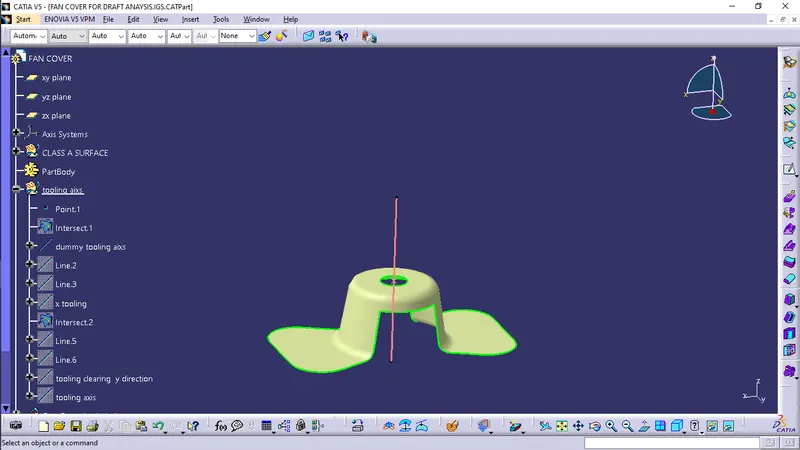
fig 1: Dummy tooling axis:
After creating the dummy tooling axis local axis system is created
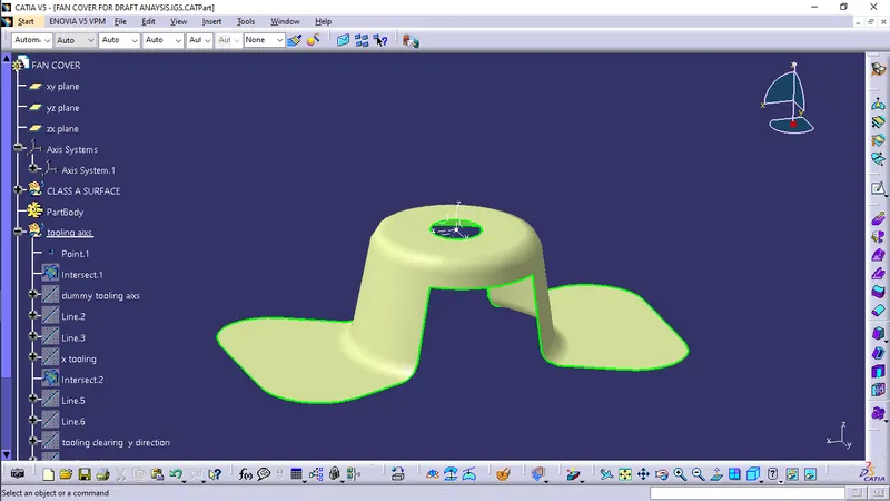
fig 2: local axis system on class A surface.
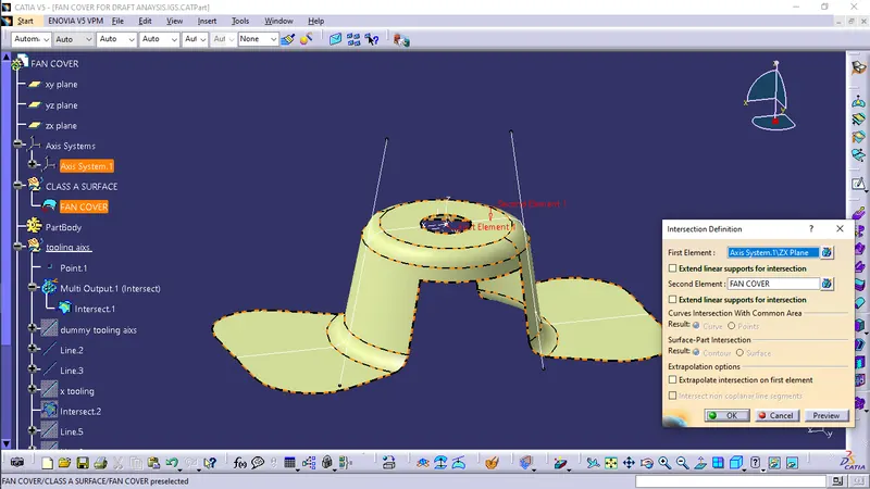
fig 3: Intersection of local XZ plane and the class A surface
After the intersection two lines are created along the tapered section of the component to ensure the draft angle is within desired range
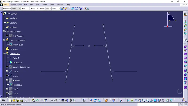
fig 4: cross section obtained from intersection & lines
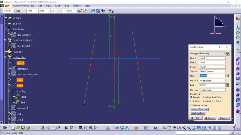
fig 5: creating a line named as x tooling which bisect the two new lines.
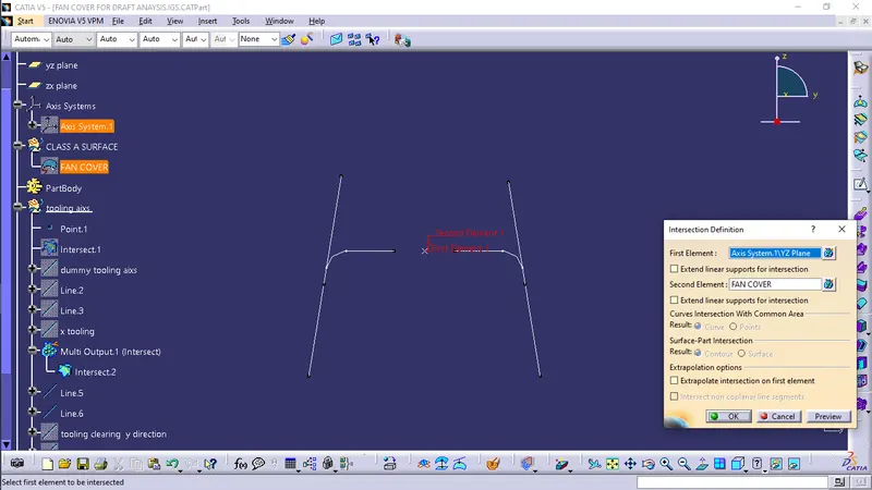
fig 6: Results from intersection of YZ plane and the axis system.
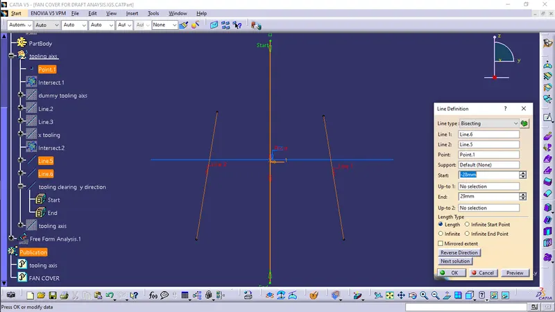
fig 7: bisecting line named as tooling clearing y direction
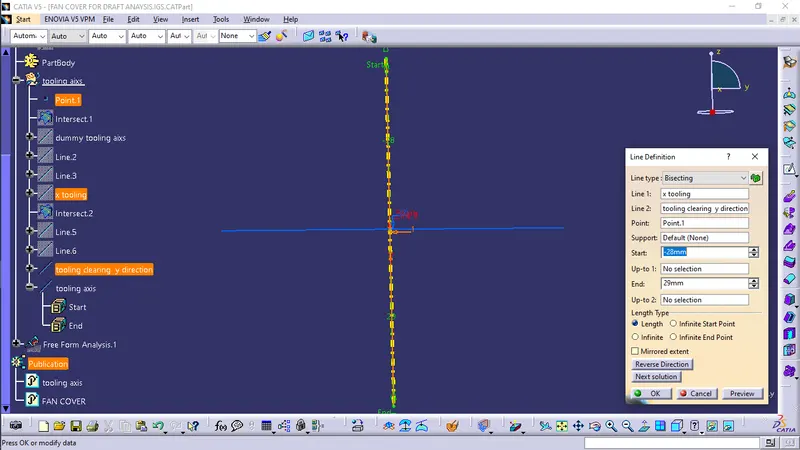
Fig 8: Final bisecting line which is defined as final tooling axis.
Step 3: Publishing the tooling axis
Finally the tooling axis is published using publishing tool in CATIA.
Step 4:
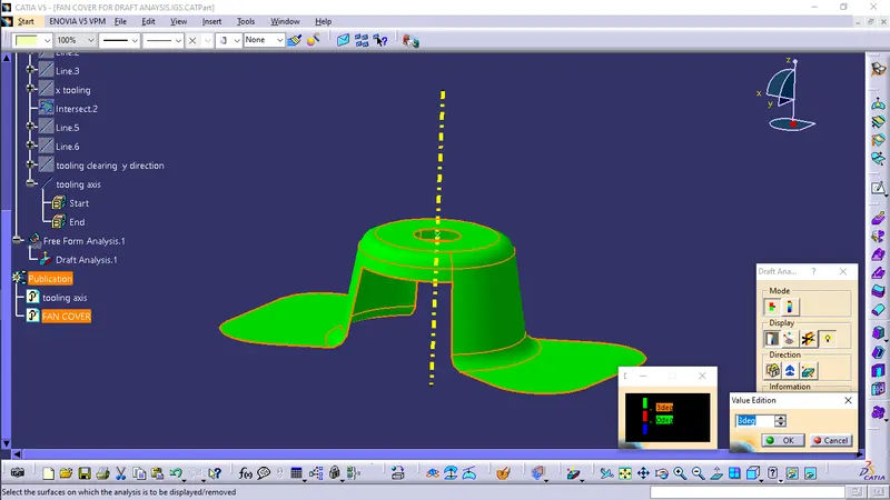
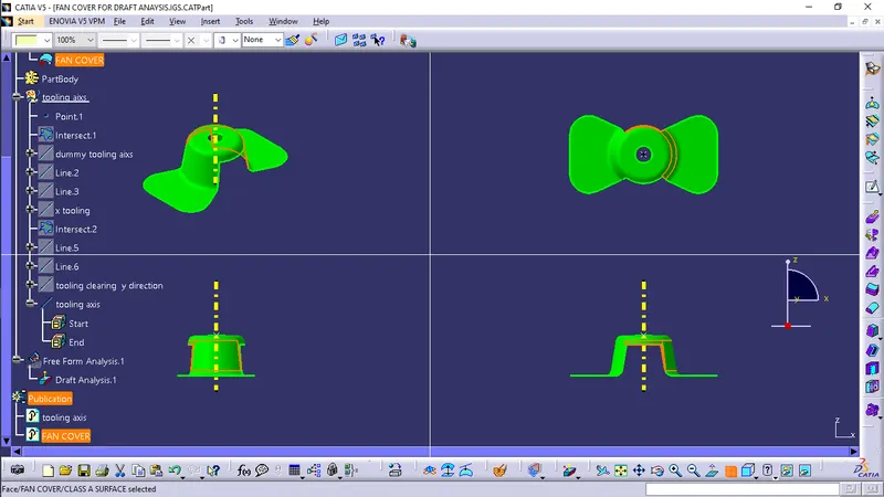
Finally draft analysis is done. The green color code ensures the draft angle is in range of desired value. For this component 3 degree draft is provided.
Color code of the draft angle in various orientations: