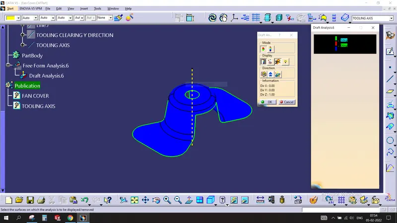
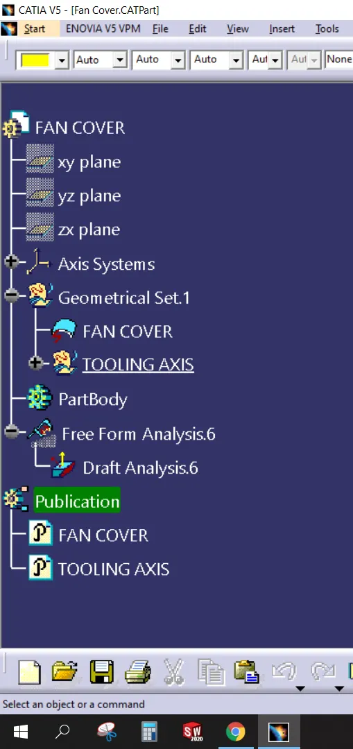
Week 8 - Challenge 1 - Draft Analysis on a Fan Cover
Draft Analysis: Every part or surface in the mould should posses a draft angle with respect to the tooling axis to eject easily from the mould and also to avoid the friction because of which there might be a poor surface finish.
Each surface in a geometry will posses some draft angle but for those surfaces whic don't have any draft angle and also not clearing the tooling axis here we need to give an minimum draft of 3 degree for easy ejection from the mould.
Draft analysis is performed on the components where ejection of the components is done and if there is NO draft is provided then the removal of the component would be diffcult.
Draft angle is provided in design stage to the components and if considerable draft is not provided then the removal of the component from the mould would be diffcult.
For the plastic component we provide a draft angle of 3 degrees and 0.5 draft angle is Ideal for the features inside the plastic component.
What is a Tooling Axis?
Tooling axis is an axis that tells the direction in which the mould or core and cavity will close or open in an Injection molding
machine.
Procedure:
- The Class A Surface is given as the input for the plastic design and in the first step we need to check for the continuity or quality of the given Class A surafce.
Here I have used Boundary command to check for the continuity of the Class A surafce.
- In the next step we need to check for the possibities of the tooling axis along x,y and z. In first case I assumed the Y direction as the tooling axis and checked for the clearance of the side surfaces of the fan
cover and the surfaces has clearance between the tooling axis but the hole in top should be cleared by another tooling axis.
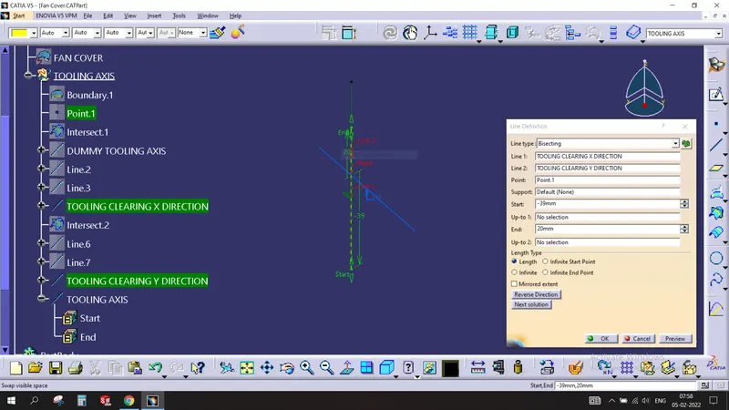
- By using the two inclined lines along the surfaces now we will draw a bisecting line and name it as TOOLING CLEARING X DIRECTION.
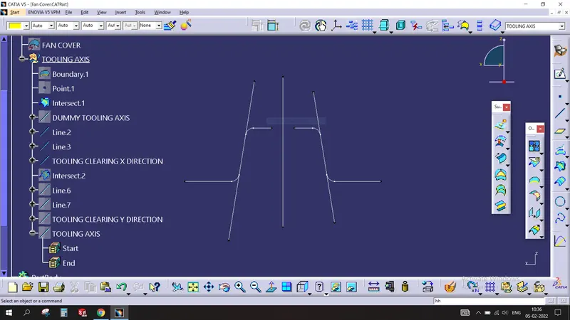
- In second case I assumed the X direction as the tooling axis and checked for the clearance of the side surfaces of the fancover and the surfaces has clearance between the tooling axis but the hole in top
should be cleared by another tooling axis.
- By using the two inclined lines along the surfaces now we will draw a bisecting line and name it as TOOLING CLEARING Y DIRECTION.
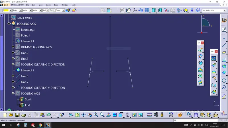
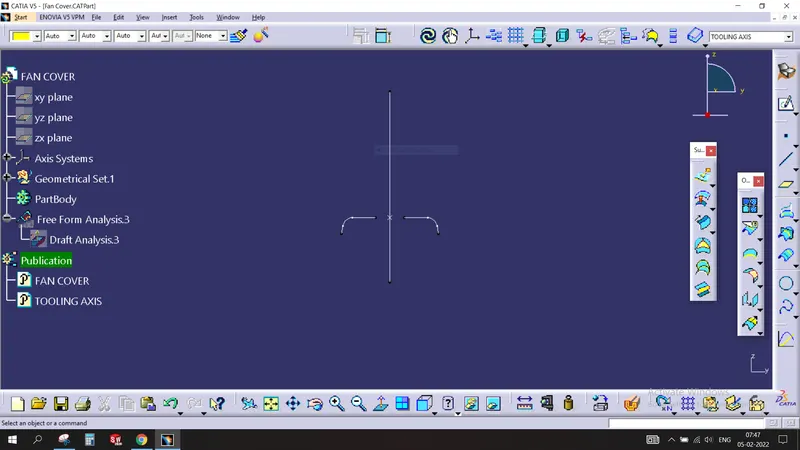
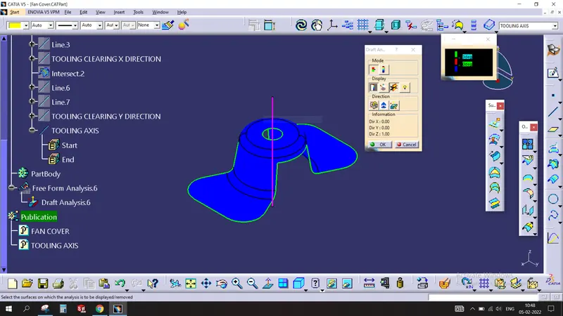
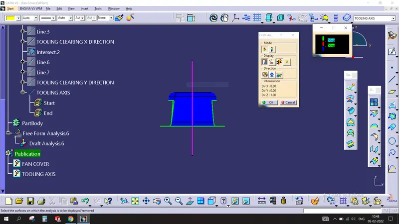
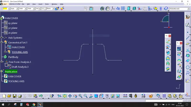
- By using the above two TOOLING CLEARING X DIRECTION and TOOLING CLEARING Y DIRECTION. here we made a tooling axis along Z direction in which the side surfaces have clearance with the tooling axis and the hole also cleared in this tooling axis.
Draft Analysis:
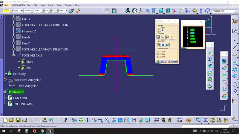
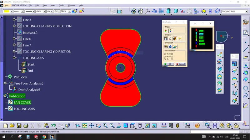
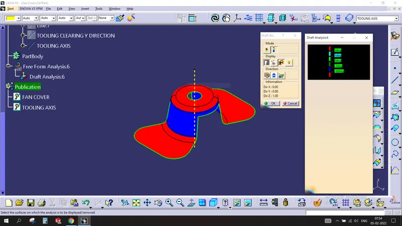
- Here Draft analysis is done to know the draft across the geometry on all surfaces with the help of colour grading by switching from the quick ananlysis and full mode analysis.
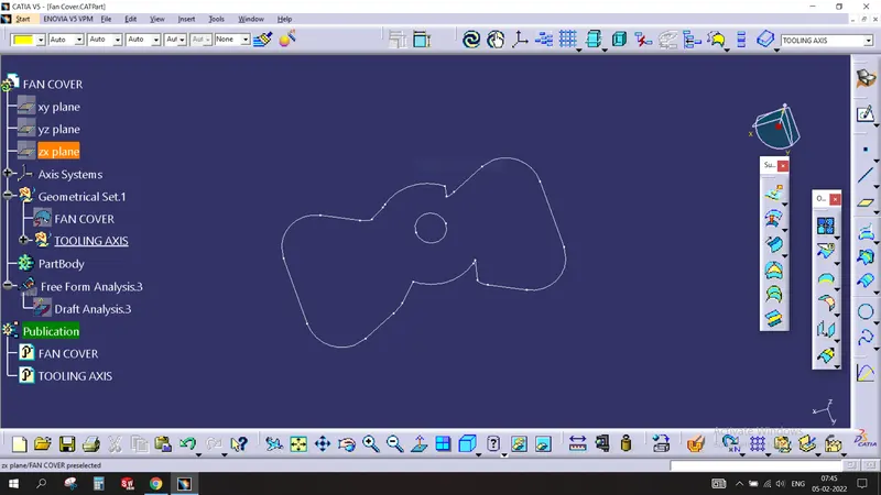
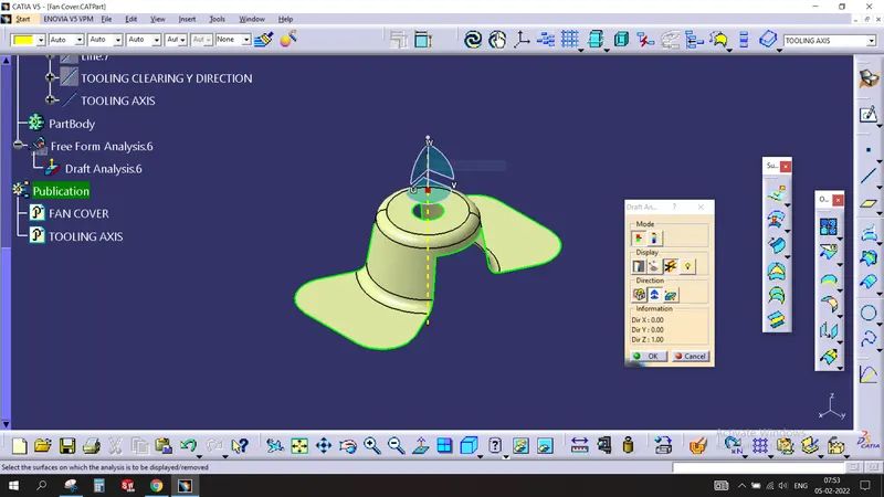
- The first step is to allign the compass to the tooling axis in that way the draft across the geometry is calculated with respect to the tooling axis,and lock the draft direction.
- Based on the color scale and playing with the values we can check for the draft on a surface.
- By using the analysis under the running point,we can check the draft angle at a specific point.