Week 8 - Challenge 1 - Draft Analysis on a Fan Cover
DRAFT ANALYSIS OF FAN COVER
Draft is the angle that is put on the side faces of the part so that the part doesn’t get trapped in the mold or cast. Here the draft angle is checked on a fan cover in CATIA V5.
The Class A surface is provided to us.
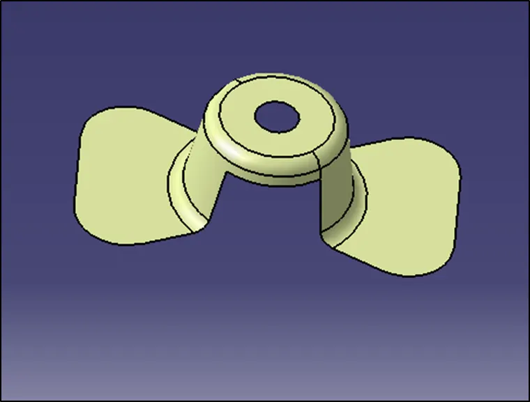
Fig 1. Class A Surface
First of all we need to check whether the surface provided has nay discontinuity in it. For that we will use the command boundary and check if there is any discontinuity in the surface.
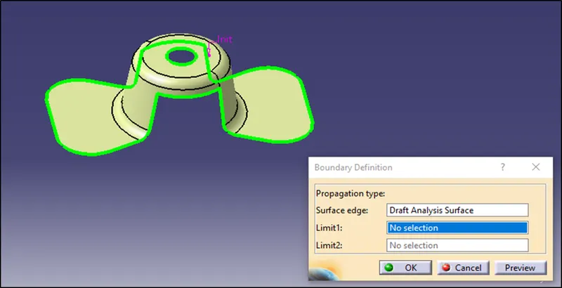
Fig 2. Checking for surface Discontinuity
After that we will join the whole surfaces of the fan cover by using join command.
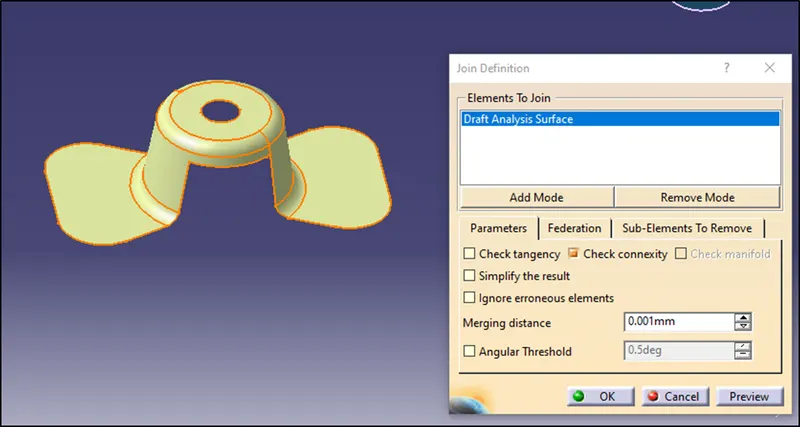
Fig 3. Join Command
Then we will randomly select the tooling axis. For making the selection first analyse the shape of the product and avoid side cores as far as possible. Here we will take the Z axis as the tooling direction and mark a point there and create a datum axis at that point. We will make a dummy tooling axis in the Z direction.
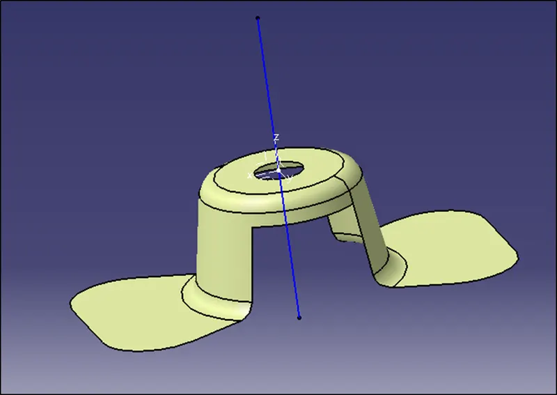
Fig 4. Dummy Tooling Axis And datum axis is created
Next step is to take the intersect of the fan cover and the XZ plane.
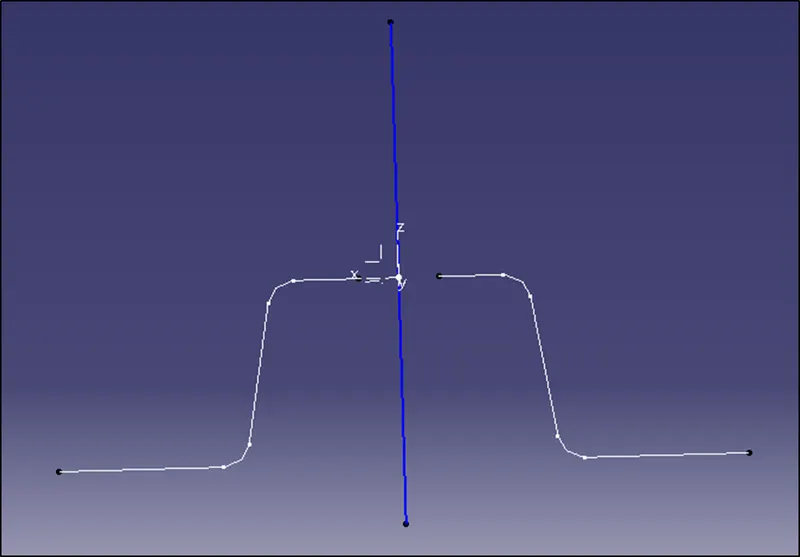
Fig 5. Intersect at XZ plane.
Observe the surfaces which are parallel to the dummy tooling axes and which will create a problem while the component will be ejected from the mould. Draw a line through the surfaces.
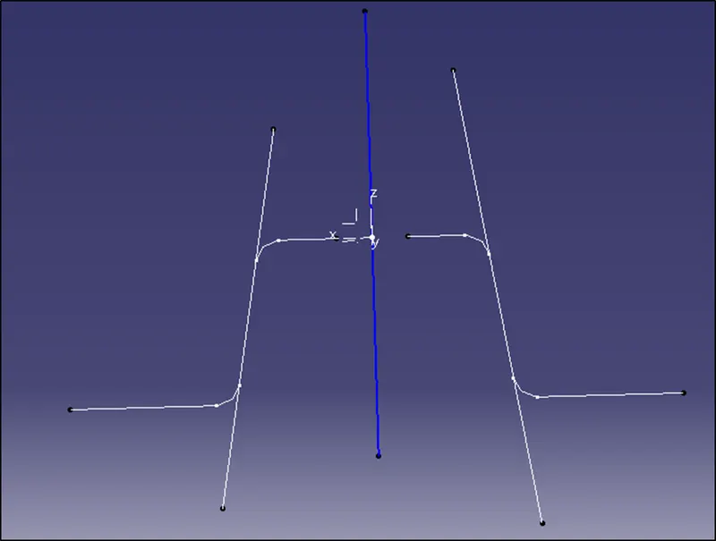
Fig 6. Extending the parallel surfaces to the dummy tooling axis
Next bisect both the lines and obtain the line that is going tin the direction of the dummy tooling axis. That will be the tooling axis in the xz direction.
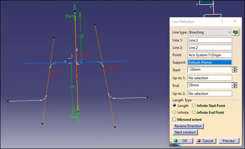
Fig 7. Bisecting the lines
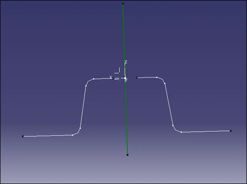
Fig 8. Tooling axis in the XZ direction
Next obtain the tooling axis for the YZ direction by following the same steps.
Take the intersect of the fan cover and the yz plane.
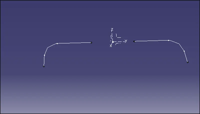
Fig 9. Intersect at YZ plane
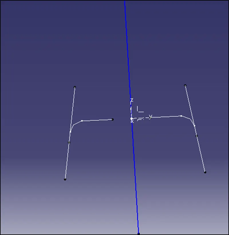
Fig 10.Extending the parallel surfaces to the dummy tooling axis
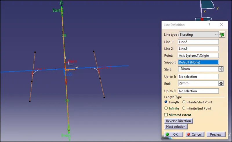
Fig 11.Bisecting the two lines
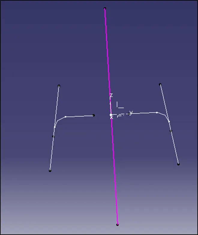
Fig 12.Tooling axis in the YZ direction
Now we have got tolling axis in the XZ and YZ direction. Bisect both the lines and obtain the line which is in the direction of the dummy tooling axis. That is the required tooling axis of the fan cover.
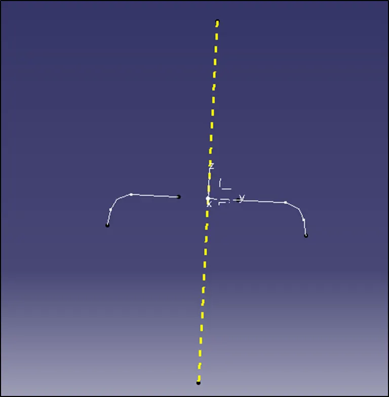
Fig 13.Required Tooling Axis of the Fan Cover
Now we have to perform the draft analysis in the required tooling direction.
Change the view to material mode in the customize view parameters.
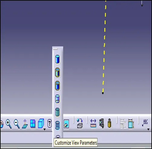
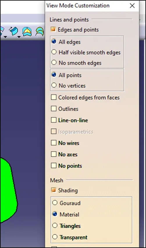
Fig 14.Material Mode for Draft Analysis
Then insert > analysis > feature draft analysis.
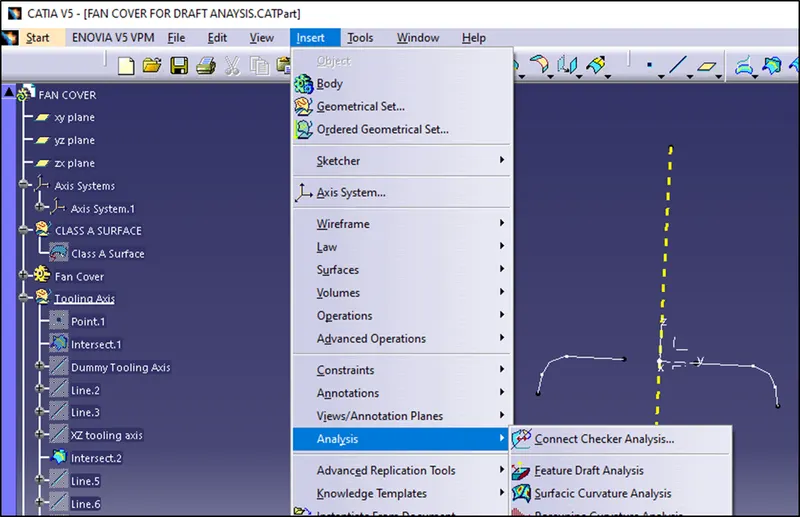
Fig 15. Draft Analysis
Next take the compass and put it over the tooling axis to get the required direction of draft analysis and then lock the draft direction.
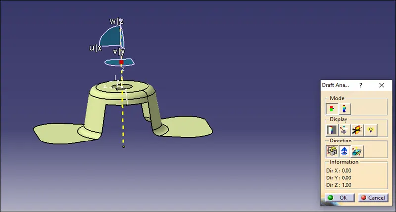
Fig 16. Compass over the tooling axis
Then double click on the component and it will show the draft analysis. It is shown according to different colours for different draft angles.
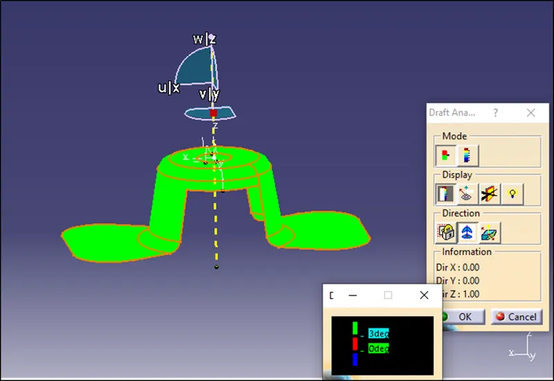
Fig 17. Draft Analysis Report
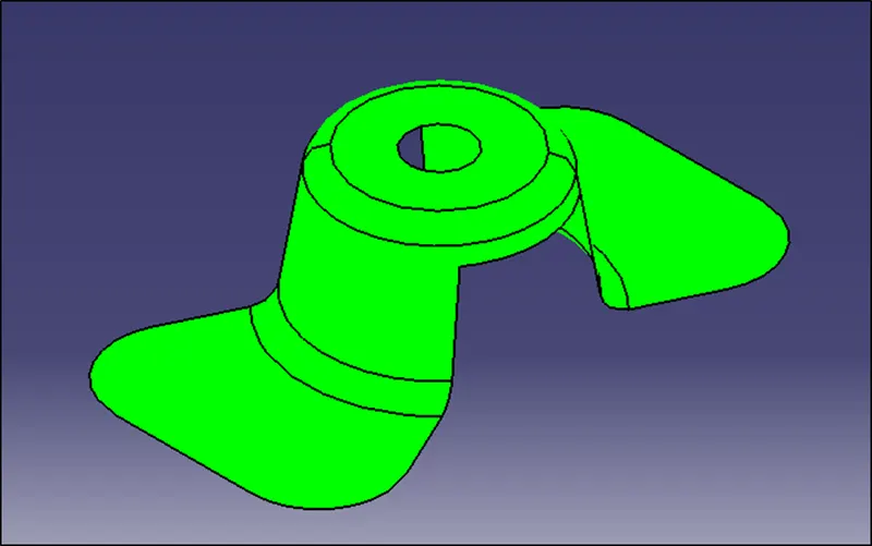
Fig 18. Isometric View
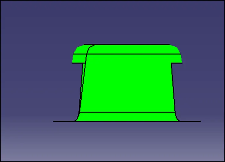
Fig 19. Front View
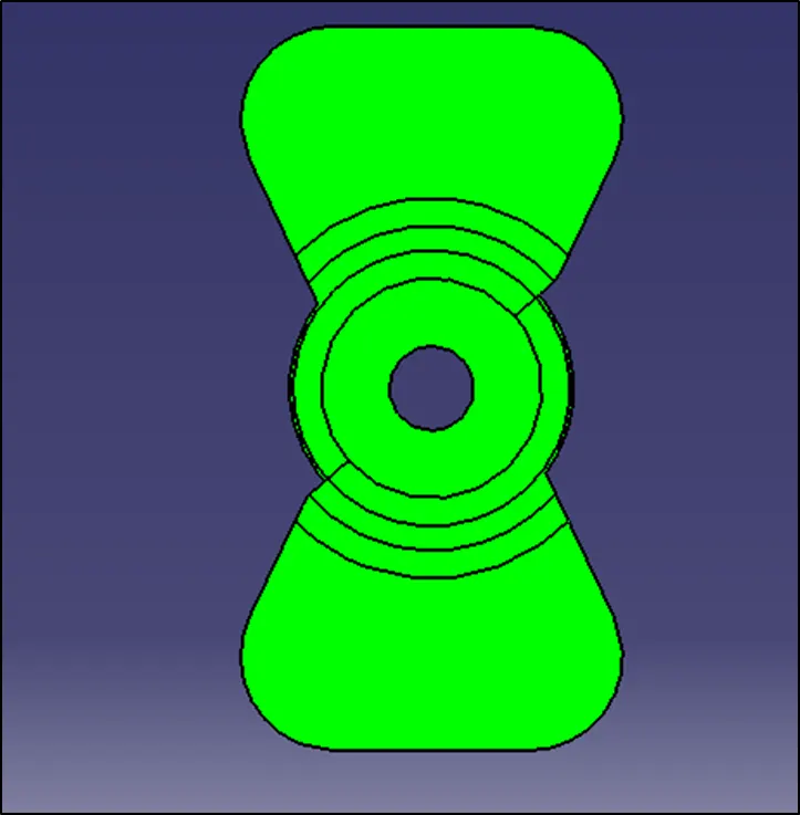
Fig 20. Top View
***********