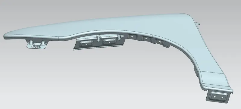
Fender Design Challenge
FENDER MOUNTING AREAS DESIGN
Introduction to Fender :
Fender is used to prevent stones and other small particles from causing damage to pedestrians and controlling the motion of these particles that will hurl when the vehicle is moving and throw them in all directions.
There are two types of fender available in market,
1) Full bumper type
2) Half bumper type
Recently we are using only half bumper type. The reason being that the first one needs a large blank adding to the high cost of the tool. The latter one reduces the blank size as well as can contribute to making two in a single blank used for the full bumper type. And also the steel used for the part is reduced which in turn reduces the weight of the product we are making. Hence Half bumper type is favourable.
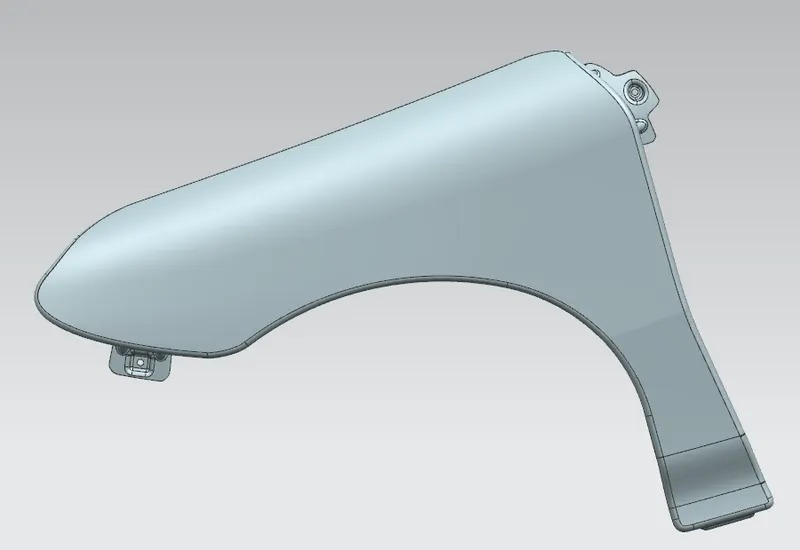
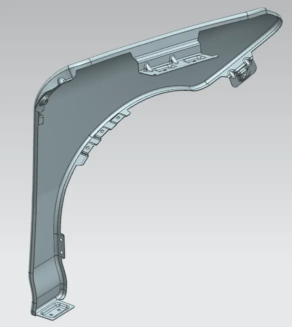
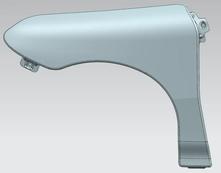
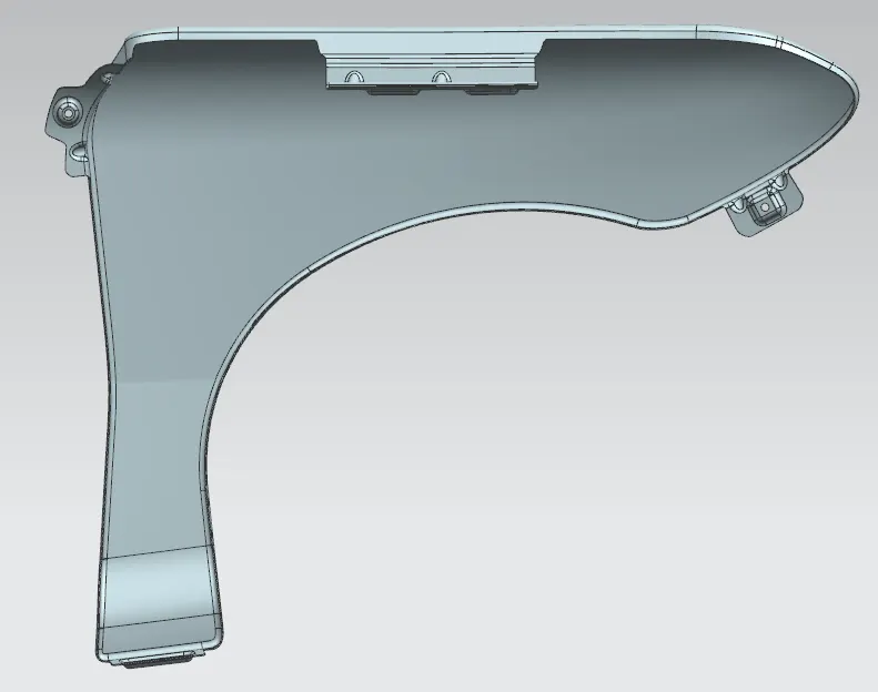
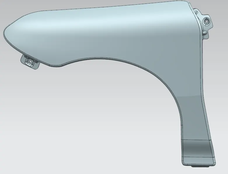
Based on the given fender skin we are going to create various mountings so that it can be fixed on the car body adjacent to Bumper , A -Pillar and Sill.
There are 5 mounting points in a fender,
1) Body
2) A-Pillar
3) Sill
4) Cowl
5) Drip
Fasteners are used to hold the fender in place. Plastic/ push pins and screws are used.
Design of various mountings are explained in detail below,
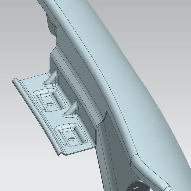
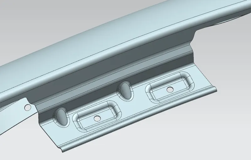
1) DRIP AREA
Drip area is the very important mounting given on the fender and it serves as a major clamping on the car engine compartment. There are some design considerations to be followed when making the drip area,
- Minimum of 200mm gap should be maintained from the Cowl and the starting of drip mounting( Inorder to provide sufficient space for the wiper motor mounts and other mechanisms on the cowl)
- Minimum of 150mm gap should be maintained from the edge of Bumper mount area to the drip area.(In order to provide sufficient space for the hosuing of the head lamp)
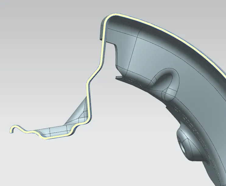
From the given master section for the drip area there are many angles followed in design. These are given to make the drawing of the sheet metal easier and also to prevent the visibility of the inner parts when peeking inside the hood.
The extreme end of the drip area should have minimum 10mm gap with the engine as per the regulation.
The fender drip area is mounted to the engine compartment using another bracket that is conncetd to the drip area.
DRIP AREA AND PEDESTRIAN SAFETY :
A minimum of 50mm distance should be maintained between the parting line of hood and fender to the side reference line(SRL). This is important because it decides the wrap around distance for pedestrian safety. When this distance is more than 50mm a request should be made to increase the hood area towards fender and satisfy the criteria.
The following design is made based on the master section given as input.
2)BODY SIDE MOUNTING
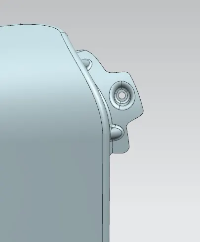
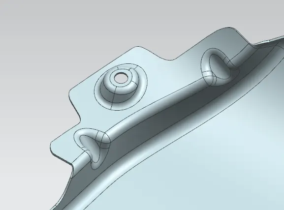
This mounting is attached to the body side of the car near the door hinges. The design of this mounting can be made only based on the near by parts(door mounting, A-pillar) input data so that these can fit together as a package.
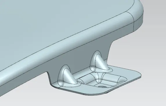
3) BUMPER MOUNTING
This mouting point is attached on the Bumper and hence designed in coordination with the bumper design. Needed reinforcements such as beads / embosses should be given.
4) SILL MOUNTING
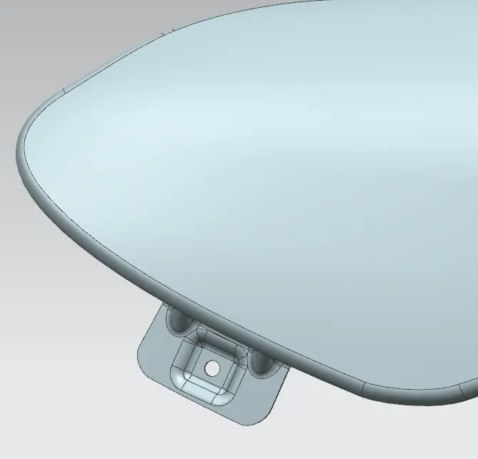
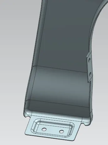
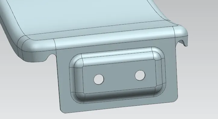
This Mounting is provided to attach the Fender to the SILL area of the car at the door bottom. Neccessary reinforments must be given to meet the strength criteria.
This area of mounting undergoes a lot a stress as the curved side of the fender meets at this particular area. Hence neccessary relief must be given as shown in the second image to minimise stress concentration and tearing of the sheet.
5)BAFFLE MOUNTING
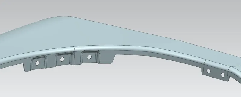
Baffle or Fender liner is the plastic part which is mounted to the fender on these mounting points. Baffle plays a major role by covering the visibility to the inside of the engine compartment and also helps stops the throwing of stones / dirt particles inside the engine area. These mountings usually have Push pins used as fasteners.
FRONTAL CRASH AND FENDER DESIGN :
Since Fender is one of the parts that is present at the front side of the vehicle, it is important to consider the frontal crash condition for the fender. Fender is also one of the parts that will be subjected to deformation in a frontal crash sitaution. There are two types of frontal crash considered for testing,
1) 25% offset at 40 Miles p/h
2) Straight front at 35 Miles p/h
In any case of the above frontal crash we must always design our fender in such a way that it dissipates the forces away from the passenger area so that we can always meet the required safety.
VARIOUS VIEWS OF THE MODEL :