Week 8 - Challenge 1 - Base Bracket Design
Aim: To create a Base Bracket Plastic Component through a given Class A Surface and perform Draft Analysis on the final plastic component.
INTRODUCTION:
- CLASS-A SURFACE:a surface made by the designer which is given as an input to the plastic modeler to work on. It is aesthetic surface and the outer most surface.
- CLASS-B SURFACE:a surface below a certain thickness from the class-A surface is class-B surface. This is the surface that contains engineering aspects of a model.
- CLASS-C SURFACE:a surface that joins class-A and class-B surfaces is class-C surface.
METHODOLOGY:
In this model we have focused on the following things:
- Tooling axis
- Draft analysis
- Class-B surface
- Class-C surface
- Making a solid model from surface.
PROCEDURE:
- Open the given CATPART and check for the gaps and boundaries of the component by using boundary option and selecting the whole component. any unwanted gaps in the model will be highlighted easily.
- The tooling axis needs to be created (the direction of the Mold input), perform all the operation in the separate geometrical set an name it accordingly.
- Firstly, create a point in the desired location and between the hole in the component.
- Create a Dummy Tooling Axis with the center point in Z direction.
- Now using the intersection option select the component and the YZ-Plane to create a intersecting lines on the component. Make sure to keep all sub elements.
- Now with the reference on the intersecting lines create another lines using point-point option and extend them accordingly.
- Now create a bisecting- line with reference of the two newly created lines and point.
- Bisecting line were used to get the exact medium so that maximum positive draft angle can be achieved.
- Finally by using the bisecting line option the tooling axis were created.
TOOLING AXIS:
- The direction in which the mould open and closes is the tooling axis.
- Check the connectivity of the surface and ensure there will be no gap between the surfaces and then define the tooling axis.
- While creating a tooling axis give the tooling axis on a flat length surface or the surface which have a hole on it.
- Create a point on the surface where we are going to create the dummy tooling axis and using line command crate an axis. If there is a circle or flat length surface which is recommended.
-
Tooling axis can be classified into Three methods
- Point and direction.
- Normal to surface.
- Bisecting method.
Bisecting method:
- In this model we use bisect method based on the requirement. This method is used for complex components.
- To use boundaries and make bisect the lines for creating a tooling axis
- To ensure the class-A surface is properly joined and has no discontinuity to it.
- To Analyze the surface for to setup tooling axis based on best suitable angle and direction.
- Create an intersection of CLASS A surface with ZX plane and from the intersection.
- Create a bisecting line using the lines shown above.
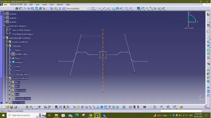
DRAFT ANALYSIS:
To perform draft analysis, click on Insert >>Analysis >> Feature Draft Analysis
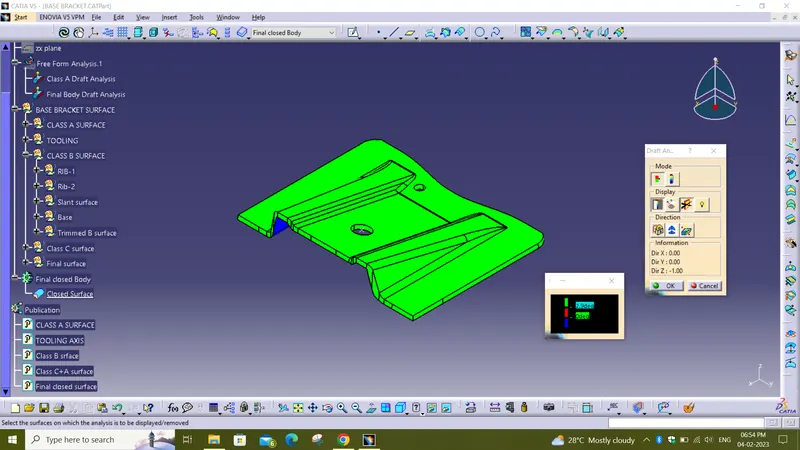
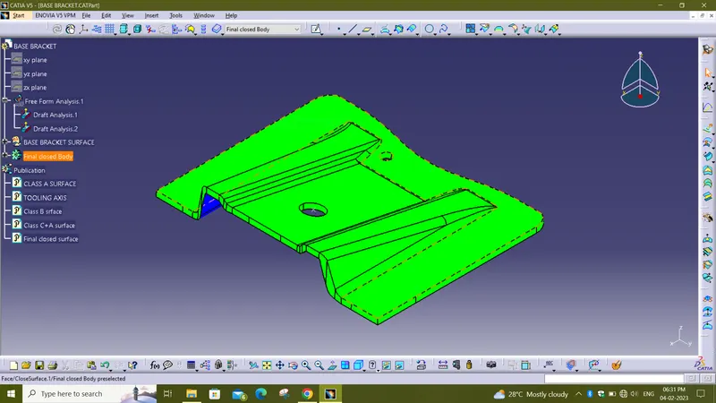
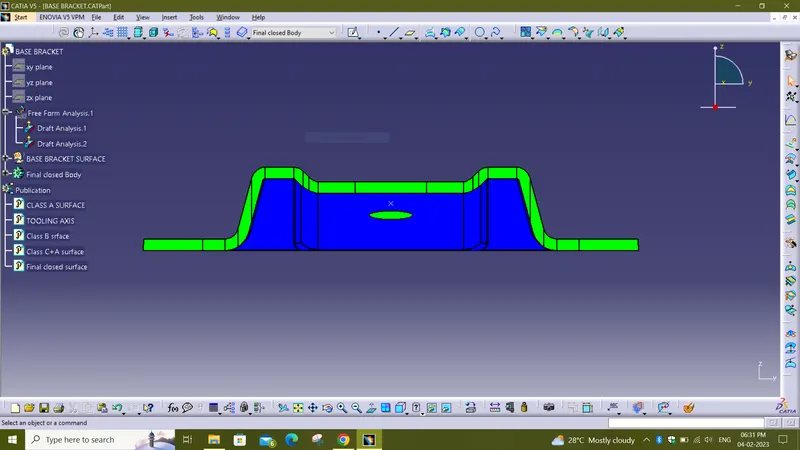
Once the draft analysis toolbar is opened, go to the display block and select the 'Analysis under the running point' command to check the angle for different sides (ribs and inclined plane angles) on the class A surface. The color scale on the bottom visualizes, whether the draft angle meets the requirements or not (3 deg) by indicating the colors Green, Blue and Red. Once the draft angle analysis was done, we need to align and fix the compass to the tooling axis of the class A surface.
DRAFT ANALYSIS ON CLASS A SURFACE:
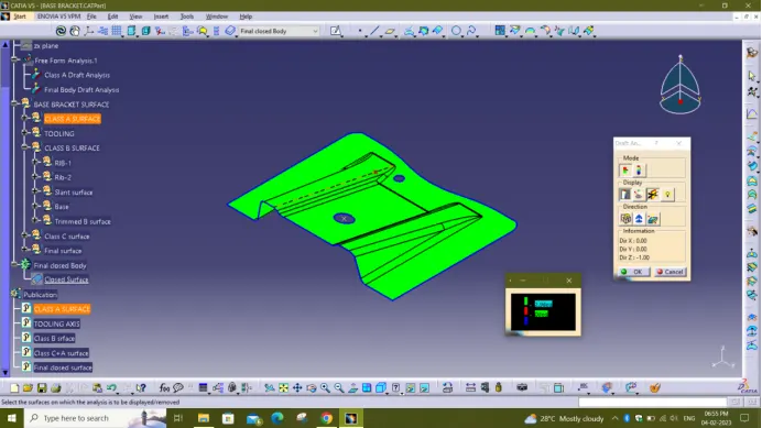
Class-A Surface:
It is the outermost surface of the automobile which gives aesthetic look to the vehicle. it is physically touchable. It is obtained from clay modelling by reverse engineering. This surface is given input to plastic product designer to work.
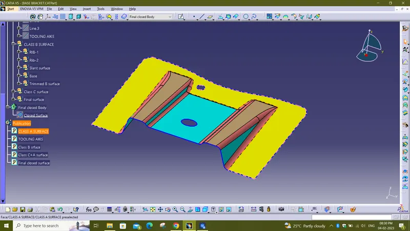
Class-B Surface:
This surface is created by taking offset from class A surface. It is the surface on which all engineering feature like screw bosses, dog house, ribs & mounting are created.
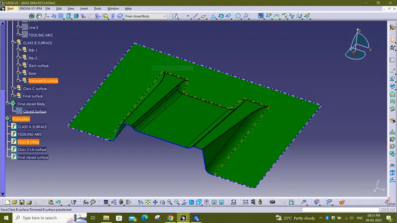
Class-C Surface:
This is the surface that joins class A & class B together.
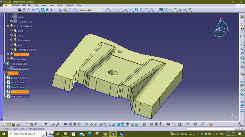
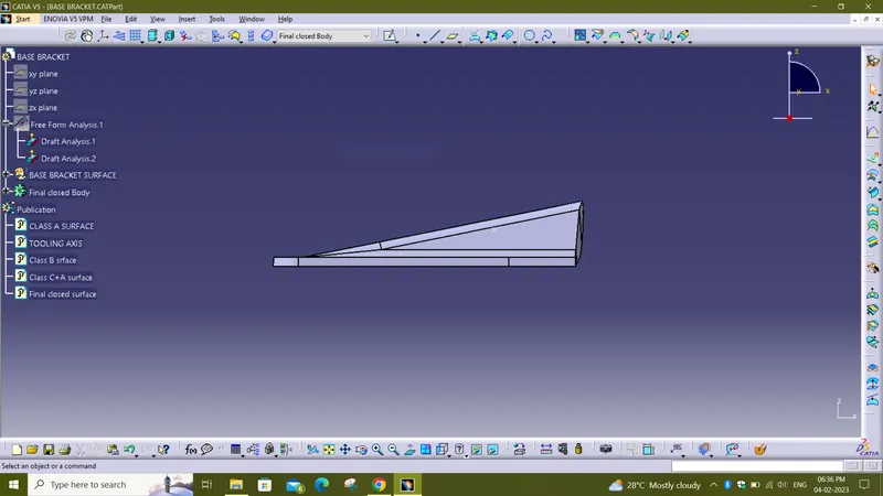
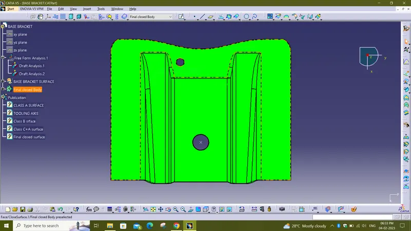
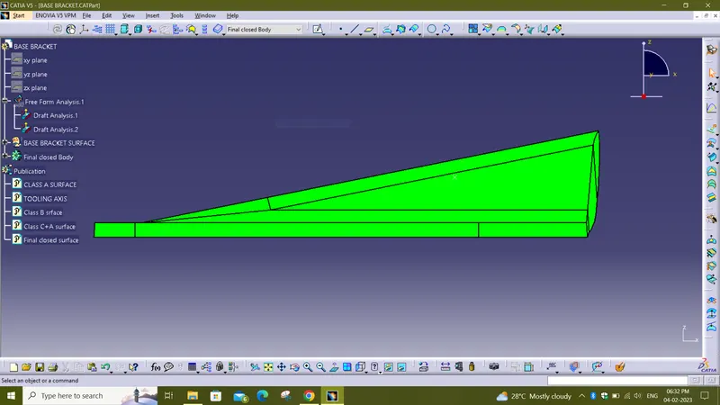
FINAL CLOSED BODY WITH DIFFERENT VIEWS:
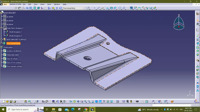
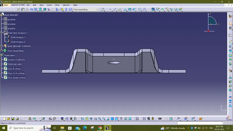
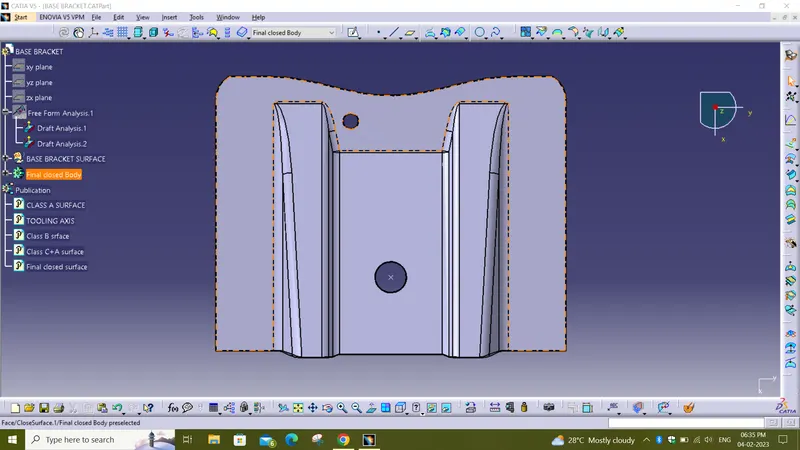
FINAL DRAFT ANALYSIS WITH DIFFERENT VIEWS:
CONCLUSION:
Created a base Bracket through a given class a surface and draft analyzed the surface with 2.9 degree of draft angle.