Week 8 - Challenge 1 - Base Bracket Design
BASE BRACKET CHALLENGE 1
OBJECTIVE
- To create base bracket plastic component from the given class- A surface.
- To create the tooling axis for the plastic component
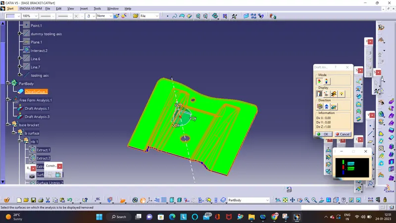
- To perform draft analysis over the plastic component.
CLASS A SURFACE
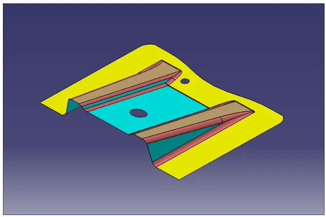
This is the given class- A surface. In which there are two holes to be crated and two ribs. These two ribs are connected by a flat surface.
In automotive design, a class A surface is any of a set of freeform surfaces of high efficiency and quality. Although, strictly, it is nothing more than
saying the surfaces have curvature and tangency alignment – to ideal aesthetical reflection quality, many people interpret class A surfaces to have
G2 (or even G3) curvature continuity to one another (see free form surface modelling).
Class A surfacing is done using computer-aided industrial design applications. Class A surface modellers are also called "digital sculptors" in the
industry. Industrial designers develop their design styling through the A-Surface, the physical surface the end user can feel, touch, see etc.
TOOLING AXIS OF THE COMPONENT
TOOLING AXIS
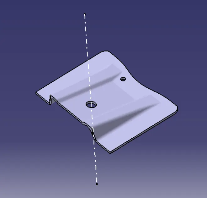
Tool axis controls the orientation of the tool axis that will be used to create the toolpath.
Tool axis — Select to define the tool orientation. The default value is Vertical, which is used for standard 3-axis machining. However, it can also be
a fixed angle or a continuously changing orientation.
DUMMY TOOLING AXIS
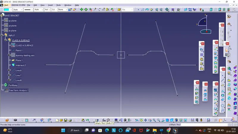
BY CREATING DUMMY TOOLING AXIS , THE EXACT POSITION OF THE TOOLING AXIS CAN BE DETERMINED AND THE TOOLING AXIS IS CREATED
AS SHOWN IN THE ABOVE PICTURE
BASE BRACKET DESIGN PROCEDURE
CLASS-B SURFACE
RIB CREATION
- Bringing in the class-A surface.
- Extracting the rib surface.
- Un-trim the extracted surface.
- Extrapolate the un-trimmed surface.
- Trim the surface as per required shape.
- Repeat step 2, 3 and 4 for the next rib surface.
- Offset the created rib surfaces for 2.5mm. ( CLASS-B SURFACE)
MIDDLE FLAT RIBS CONNECTING SURFACE
- Extract the middle flat connecting surface from class-A.
- Un-trim the extracted surface.
- Extrapolate the un-trimmed surface.
- Offset the extrapolated untrimmed surface for 2.5mm.
- Trim the surfaces. (CLASS-B SURFACE)
CREATION OF BASE SURFACE
- Extract the base surface from class-A surface.
- Un-trim the base surface.
- Extrapolate the base surface.
- Offset he base surface for 2.5mm
- Trim the base surface from the middle surface which is already created.
JOIN
- Join all the class-B surfaces to make as one unit.
FILLET
- Since the class-B surface is 2.5mm downwards to the class-A surface need to add this offset distance with the filleting radius observed from the class-A surface.
CLASS-C SURFACE
This the connecting surface of class-A and class-B surfaces.
- Create the boundary of class-A surface using boundary command.
- Use sweep command to generate class-C surface along the draft direction with 3 degrees drafting angle with respect to the tooling axis.
- Extrapolate the hole features from class-A surface and trim them.
CLOSED SURFACE
- Publish class-A, class-B, class-C surfaces and tooling axis.
- Join all the surface together.
- Create closed surface.
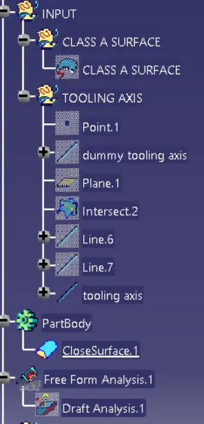
TREE STRUTURE OF COMPONENT
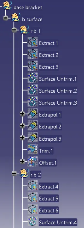
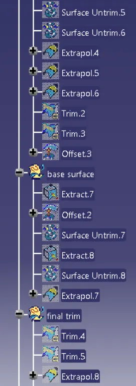
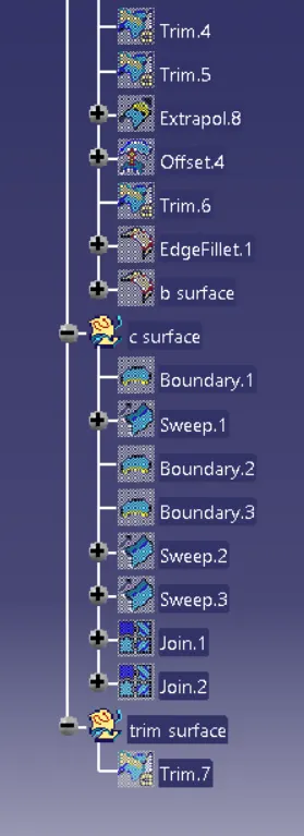
3D VIEWS OF THE COMPONENT
ISOMETRIC VIEW
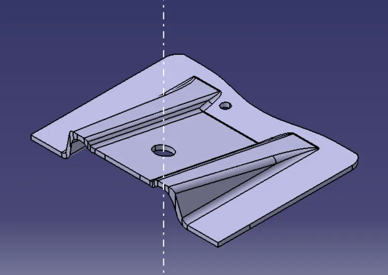
FRONT VIEW
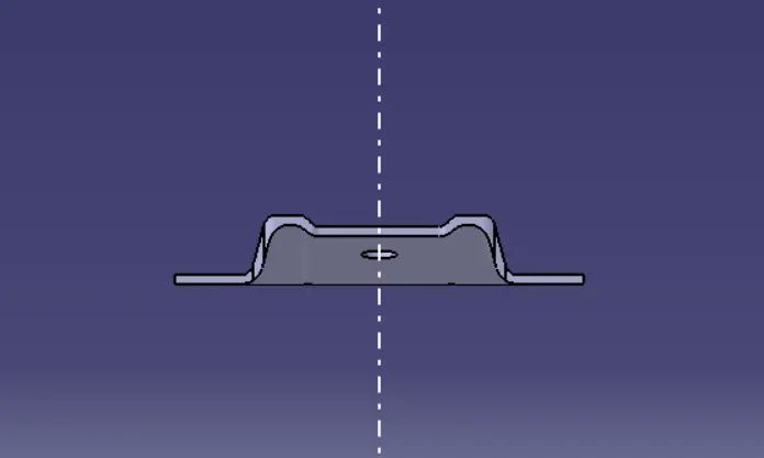
SIDE VIEW
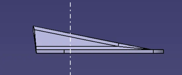
TOP VIEW
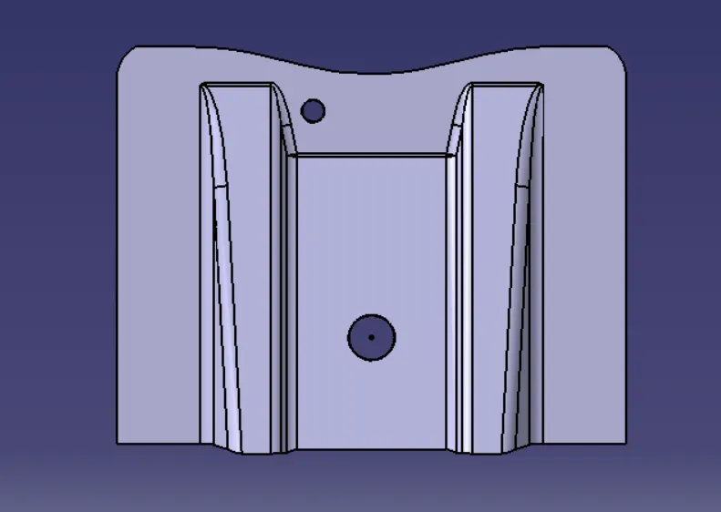
DRAFT ANALYSIS
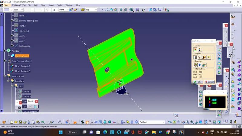
DRAFT ANALYSIS FROM TOOLING AXIS OF THE BODY
CONCLUSION
WITH THE HELP OF CATIA V5 BASE BRACKET DESIGN IS DONE