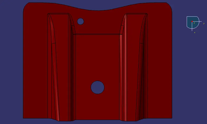
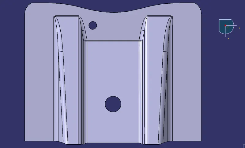
Week 8 - Challenge 1 - Base Bracket Design
Aim: To Create the Base Bracket Plastic component through the given Class-A surface. To begin with, the tooling axis for the given Class-A Surface should be created meeting the draft angle requirements and performing the draft analysis on the model at the end.
Steps to perform the given task :
- Create a Tooling axis and perform a draft analysis for a given model
- Create Class B Surface from class A Surface.
- Create Class C Surface.
- Create a solid body using the close surface command.
Create a Tooling axis and perform a draft analysis for the given model :
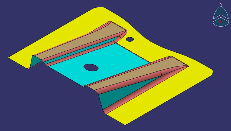
- To Create a tooling axis :
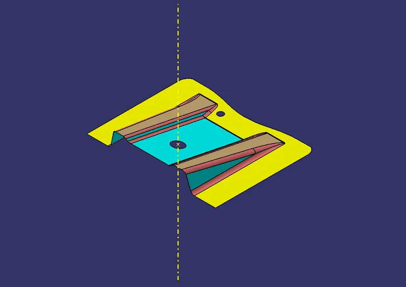
- Create a dummy tooling axis using any hole or simple structure as a reference.
- Place the point for the available hole of the CLASS-A surface, then create the line using the point in Z-Direction.
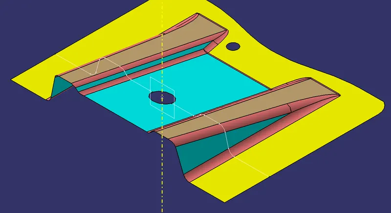
- Create an intersection between the part and a plane (Drafting can be expected to be difficult)
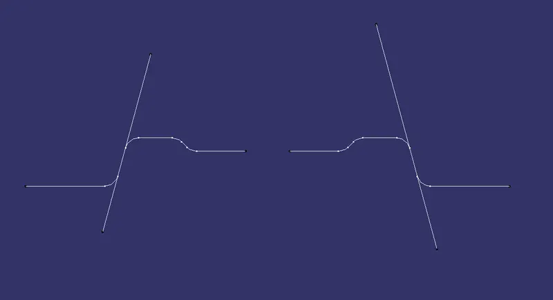
- Taking any two lines which might create a problem for tooling direction, a line is created coinciding these lines.
- The bisecting line is created between these two lines.
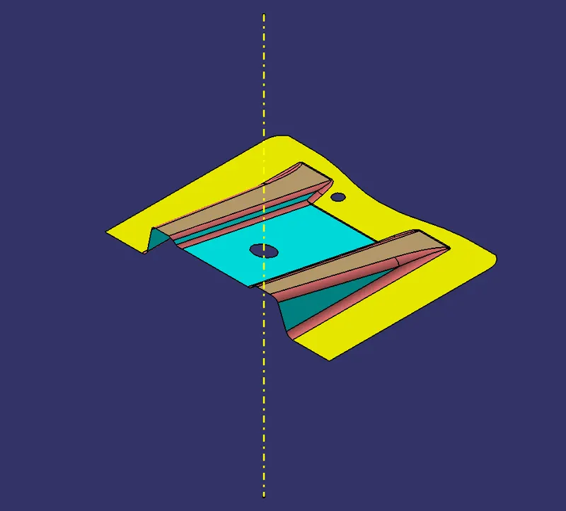
- The bisecting line is taken as the Actual Tooling axis.
POINT PLACEMENT:
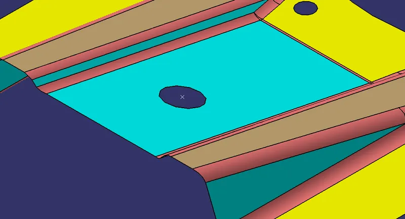
DUMMY TOOLING AXIS:
INTERSECTION of PART and PLANE:
BISECTOR LINES:
MAIN TOOLING AXIS:
Performing Draft Analysis :
Draft analysis is performed using the tooling axis as the tooling direction
The maximum draft angle that should be considered is 3 degrees and the minimum draft angle that should be considered is 0.5 degrees.
The value obtained less than 3 will be highlighted in red, These regions' Drafting is not possible. Hence, The Tooling axis should be changed or an additional process is to be done to produce the part.
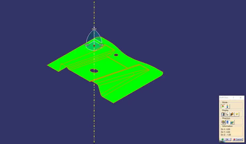
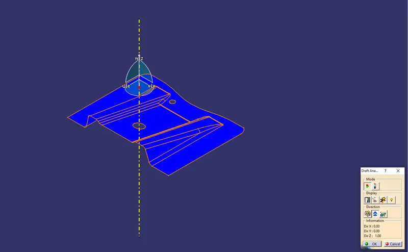
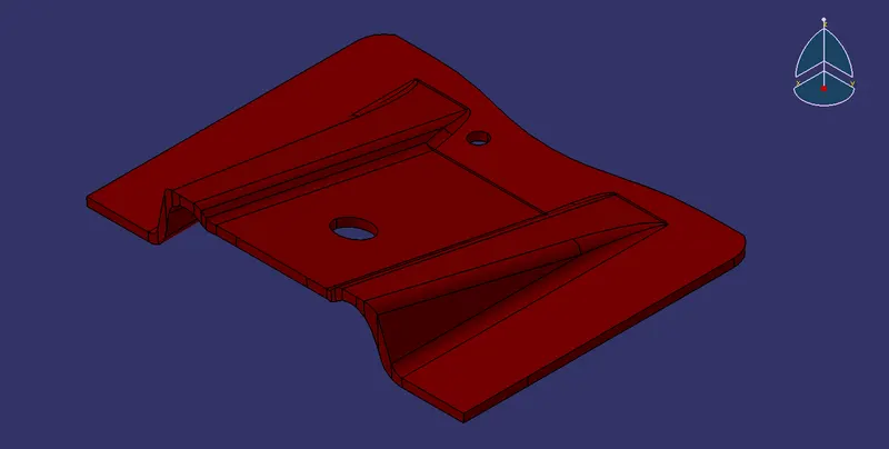
CLASS A SURFACE:
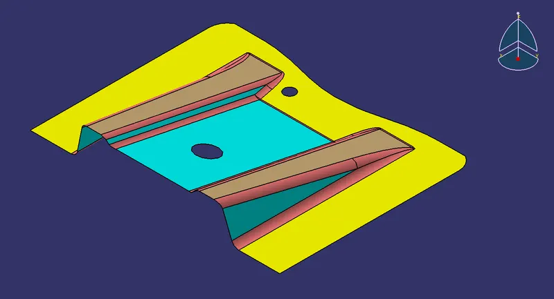
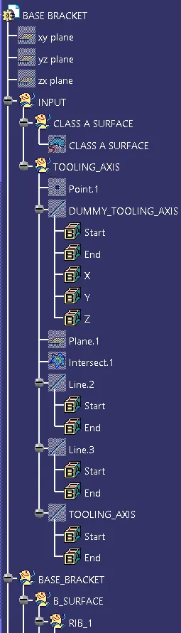
Create Class B Surface from class A Surface :
- A set of processes is to be done to obtain a class B Surface from a given Class A Surface.
- This set of processes is given in the tree structure below:
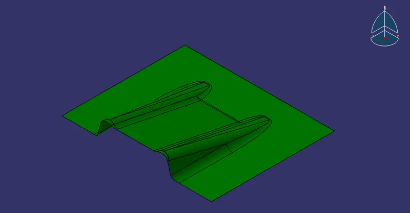
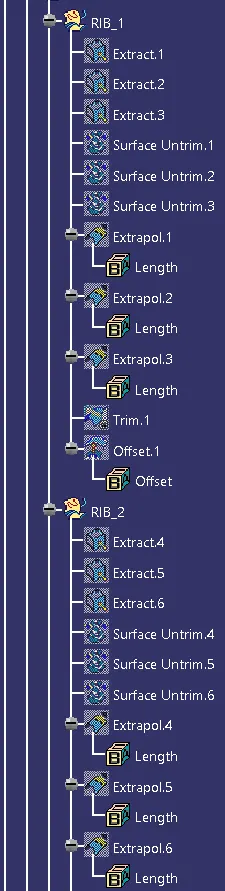
Create Class C Surface from class A Surface :
- A set of processes is to be done to obtain a class C Surface from a given Class A Surface.
- This set of processes is given in the tree structure below:
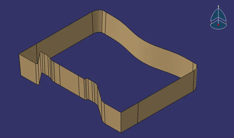
FINAL TRIM SURFACE:
TREE STRUCTURE:
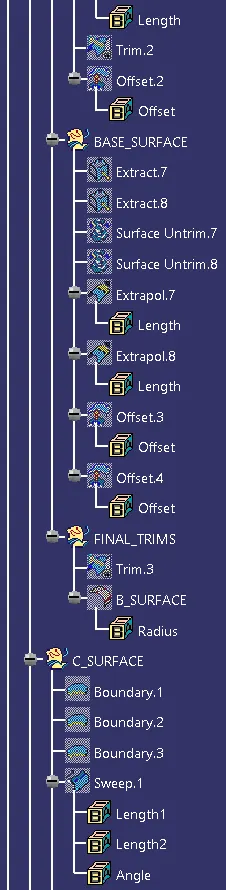
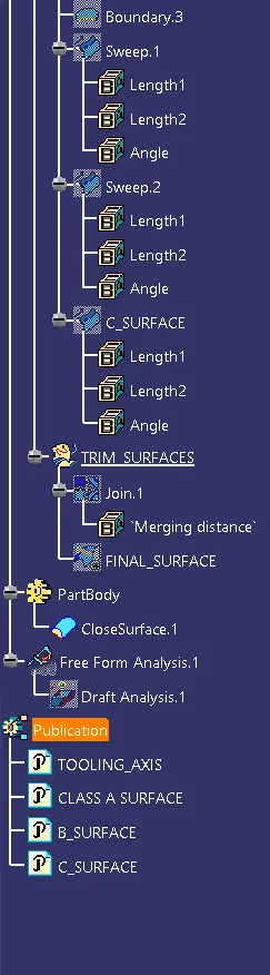
ISOMETRIC VIEW :
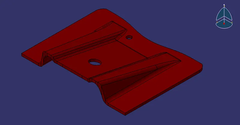
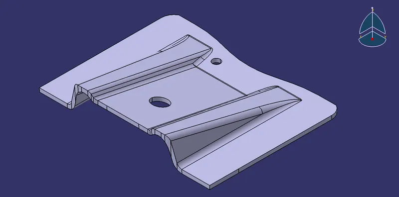
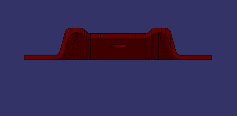
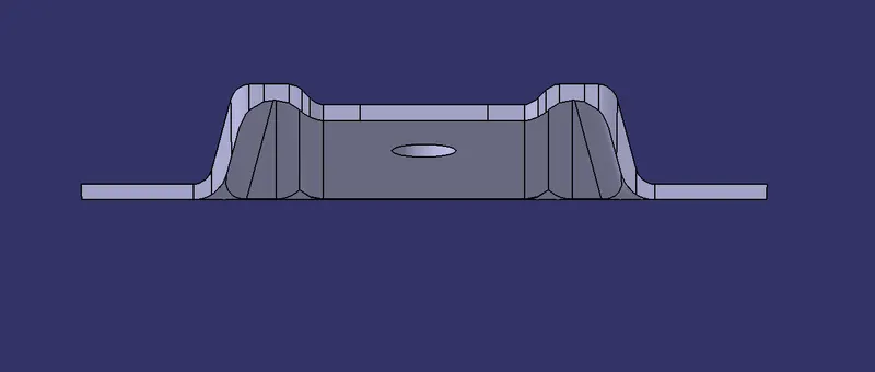
FRONT VIEW :
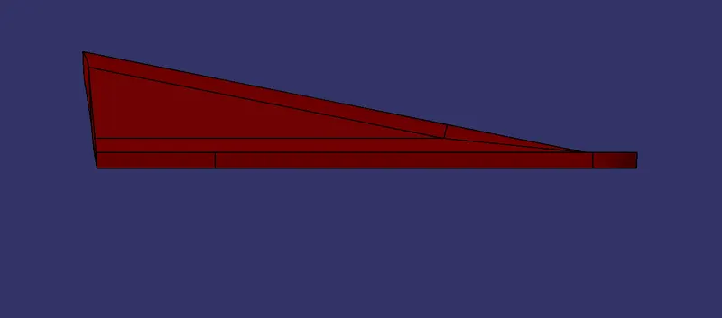
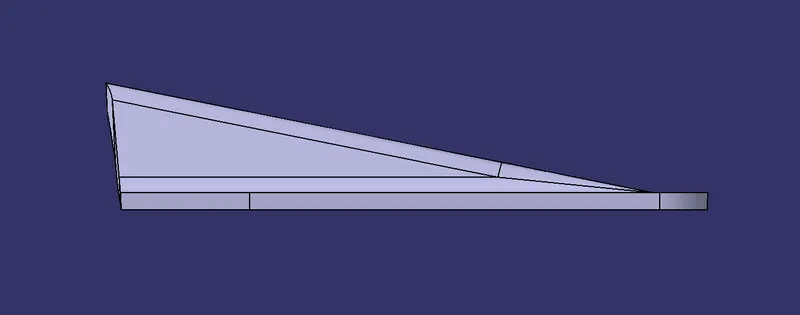
SIDE VIEW :
TOP VIEW :