Week 8 - Challenge 1 - Base Bracket Design
AIM: Create the Base Bracket Plastic component through the given Class-A surface. To begin with, the tooling axis for the given Class-A Surface should be created meeting the requirements of the draft angle and at the end perform the Draft analysis on the model.
objective:
- Tree Structure
- Ensure Proper Tree Structure
- Geometrical sets should have a proper name based on the sketches present inside of it
- All the sketches should be created under the Geometrical set
- Use the Close Surface feature to make a solid body from the surface.
- Publications: Use the publication option and publish the below
- Tooling Axis
- Class A, B, and C surface
Introduction:
CLASS-A SURFACE: the class-A surface is used in the automotive design industry. it describes the final production surface data for the aesthetic parts.
CLASS-B SURFACE: the class-B surface is the second surface that has a certain thickness from the class-A surface. this surface contains engineering aspects of a model. These must be smooth and "error-free" as well but are not held to the standards that class A surfaces are.
CLASS-C SURFACE: The Class C finish allows more imperfections than Class A or B. Class C is often specified for interior surfaces not readily visible, surfaces that will be covered by another part when assembled, or surfaces.
Draft analysis:
Draft analysis is required to check if a part has required draft or not. Draft is required so that a part can be ejected from its mould.
Design methodology:
Insert the class A surface of the Base Bracket in CATIA software.
Determining the tooling axis for the Base Bracke
Creation of class B surface.
Creation of class c surface.
Join the Base Brackes class A, class B, and class c surfaces and ensure all the surfaces are closed surfaces.
Use the Close Surface feature to make a solid body from the surface.
finally, Perform the Draft analysis on the Base Bracke final plastic component.
class A surface :
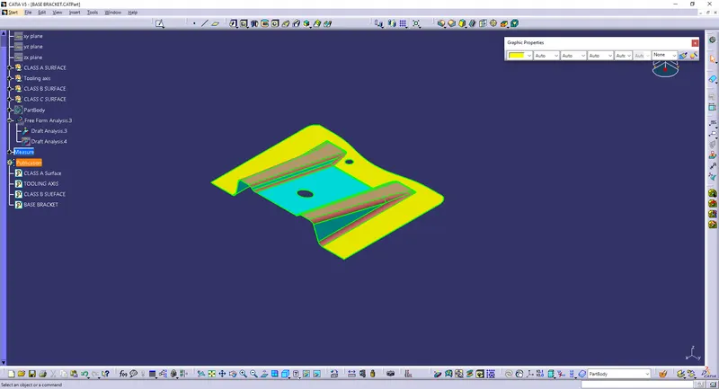
STEP 1: Check the connectivity of the Class A Surface
- Ensure that there is no gap between the component, using join command.
- We can visually check it or by clicking boundary command.
- It has 3 boundaries one outer and two inner circle boundaries.
Therefore first check completed.
STEP 2: Find the tooling axis of the component. The tooling axis is nothing but the mould opens or cavity opens.
- Check visaully which is the best possible tooling axis.
- Check all three axis.
- Along x it possible but expensive and y is not possible.
- z is the best possible tooling axis.
Creating a Tooling axis along z:
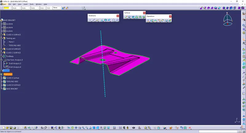
tooling axis are two method:
1. Bisecting method
2. Normal to surface
i follow normal to surface method. creatr a point at centre of hole and create a line in the point
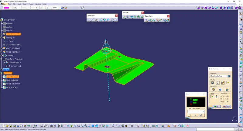
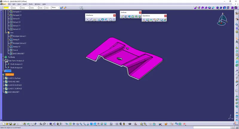
Now perform the Draft analysis using the Featured Draft Analysis tool in the tools.
Then after opening the draft analysis tool box go for the compass and place the compass alinged to tooling axis and click on the lock symbol after alinging and further click on the surface.
Now creating Class B Surface:
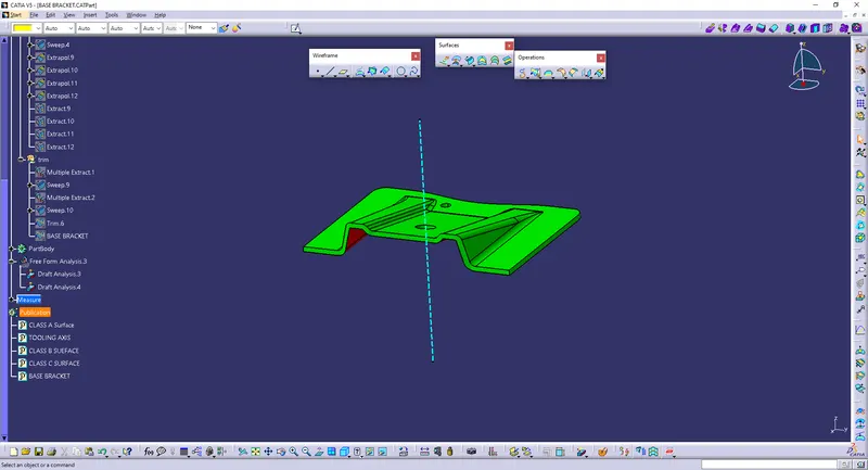
Intially extracting the flat surfaces using extract option from Class A surface.
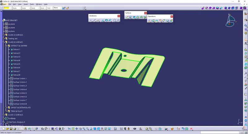
Then perform Untrim option:
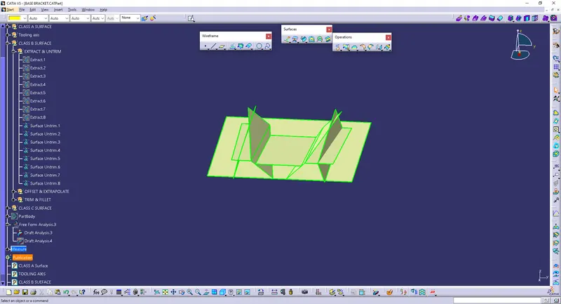
Then Offset the surface inorder to get the required thickness:
Then perform Extrapolate inorder to increase the length:
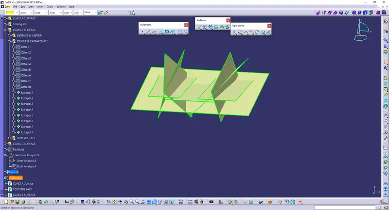
Now trim the surfaces to required surfaces:
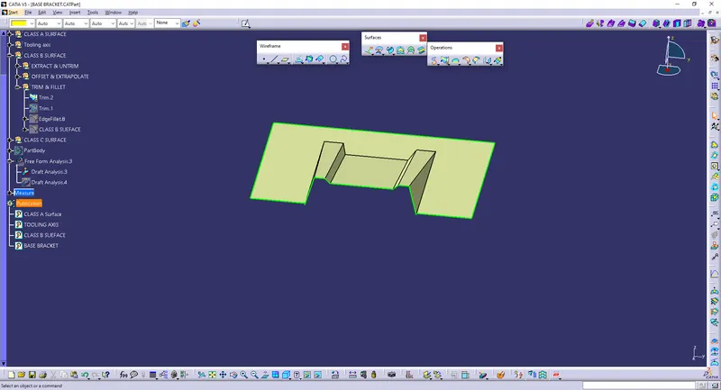
Now fillet the surface to required amount:
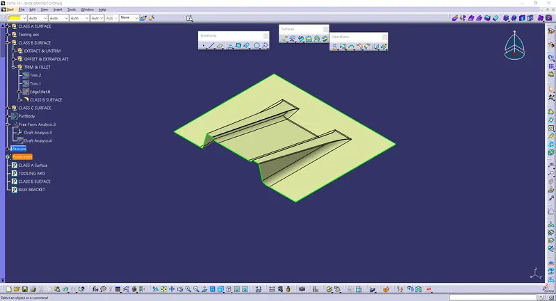
Now Creating Class C Surface:
class a surface take boundary and sweep the draft angle
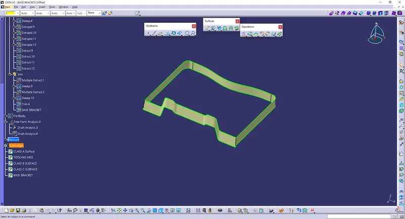
and the last process trim the class A,B and C surface then get the final product
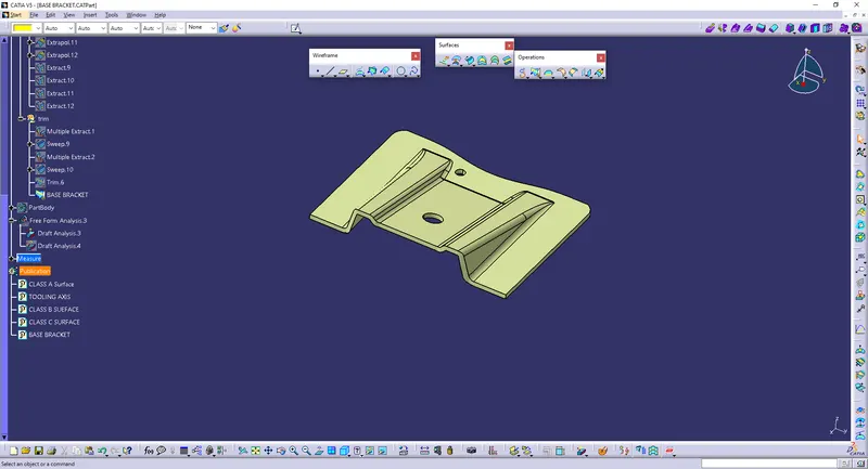
Now convert solid model
In the method closed surface method
Material:
Polyester is a category of polymers that contain the ester functional group in every repeat unit of their main chain. As a specific material, it most commonly refers to a type called polyethylene terephthalate (PET).
Uses:
Polyester fiber can be used in many forms in the automotive industry, such as knitted, woven or nonwoven fabrics, especially needle punch and stitch bond fabrics used as facing materials; woven fabrics in the airbags and seat belts;
CONCLUSION:-
Finally the Class – A, B&C surfaces with the Tooling Direction have been Published and the Base Bracket is moved on to the designing of the next operation – the creation of B-side features.