Week 8 - Challenge 1 - Base Bracket Design
AIM: Create the Base Bracket Plastic component through the given Class-A surface. To begin with, the tooling axis for the given Class-A Surface should be created meeting the requirements of the draft angle and at the end perform the Draft analysis on the model.
Objective :
- Create Tooling axis
- Create Draft Analysis for Class A Surface
- Create Class B surface
- Create Class C surface
- Create Final Product
Features used for design A-Class, B-Class, and C-Class.
- Line
- Point
- Axis system
- Extrude
- untrim
- extrapolate
- Extract
- boundary
- Join
- Sweep
- fillet
- close surface
- Intersecting
- publication
- Draft analysis
Procedure for design A-Class, B-Class, and C-Class of Base Bracket.
- Extract and then untrim, Extrapolate and trim the base bracket.
- Extract 2nd base same as Extract 1.
- offset Extract 1 and Extract 2 by 2.5mm.
- Extract and offset both the supportive base surface.
- Provide untrim and extrapolate and offset by 2.5mm.
- Apply Fillet and Rename as B-Class surface.
- Sweep A-class Surface to the 3-degree downside with draft direction.
- Join sweep and A-Class Surface then trim with B-class surface.
- Change into the close body for appropriate output.
MATERIAL SLECTION :
- THERMOSET PLASTIC.
WHERE IT IS USED ?
- It is used in the hydralic cylinder mounting area in the car bonet.
Class A Surface
A-Class surface is a term used in plastic product design. That means the surface of a component that is smooth( aesthetic) or visible side to the human eye after the part is assembled. it refers to those surfaces which are visible and abide by the physical meaning of a product.
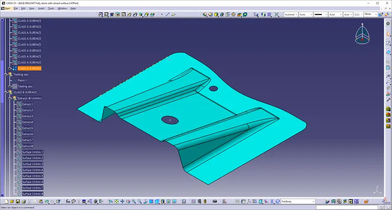
STEP 1: Check the connectivity of the Class A Surface
Ensure that there is no gap between the component, using join command.
We can visually check it or by clicking boundary command.
It has 3 boundaries one outer and two inner circle boundaries.
Therefore first check completed.
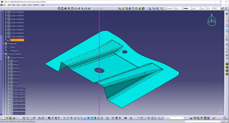
STEP 2: Find the tooling axis of the component. The tooling axis is nothing but the mould opens or cavity opens.
Check visaully which is the best possible tooling axis.
Check all three axis.
Along x it possible but expensive and y is not possible.
z is the best possible tooling axis.
Draft Analysis
The Draft Analysis command enables you to detect if the part you drafted will be easily removed. This type of analysis is performed based on color ranges identifying zones on the analyzed element where the deviation from the draft direction at any point corresponds to specified values.
In the molding process the molded parts have to eject from the die so there are some issues while removing the molded parts it may get sticky with the die, or while removing chances to get damaged, so we need to set up is the draft angle this draft angle helps the molded parts to eject from the die easily. the standard of OEM for the plastic components draft angle should be in 3 degrees and if it is sheet metal component 7 degree should be the draft angle, This draft is get analyzed and ensuring the part is with proper draft angles.
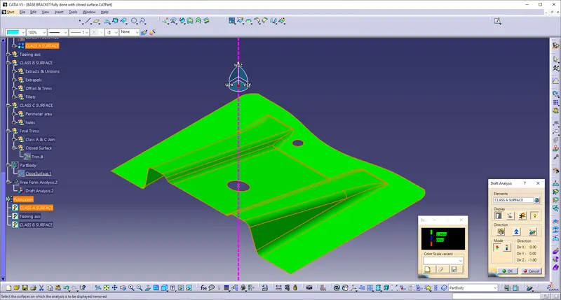
DRAFT ANALYSIS 2:
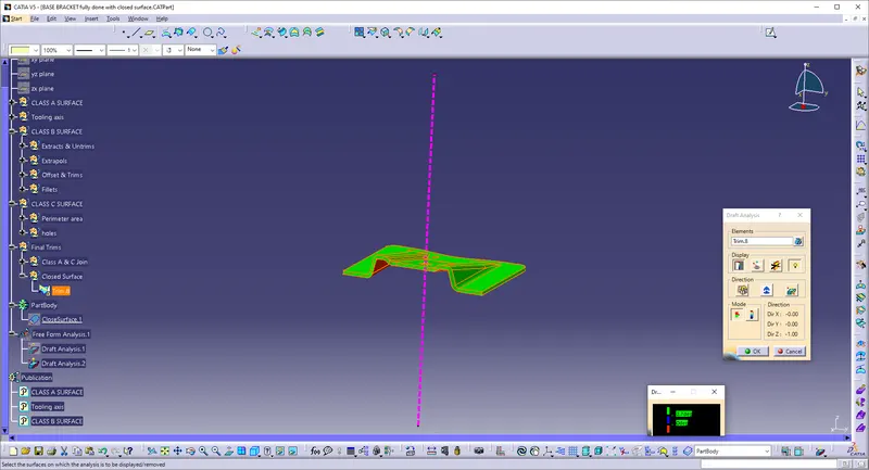
Procedure for Features Draft Analysis
- Before performing the draft analysis we create the Main tooling axis then the procedure.
- {Go to menu bar > select insert > Analysis > Feature Draft Analysis} .
- Now, align the compass z-direction with the main tooling axis which we created in the previous steps.
- Now, open the color scale and enter the value as 3 deg.
- Now hover the cursor over the body to check if every face has an angle greater than the given angle.
- Also, if the whole body is in green color it means that the value at all the faces is greater than the provided angle.
Creating a Tooling axis:
Therefore the main tooling axis is along z axis.
Now perform the Draft analysis using the Featured Draft Analysis tool in the tools.
Then after opening the draft analysis tool box go for the compass and place the compass alinged to tooling axis and click on the lock symbol after alinging and further click on the surface.
Class B Surface
B-Class surfaces are the secondary surfaces that you can see sometimes, but are less important, such as the inside of your glove box, ashtray, etc... These must be smooth and "error-free" as well but are not held to the standards that class A surfaces are. it also means the thickness of a part.
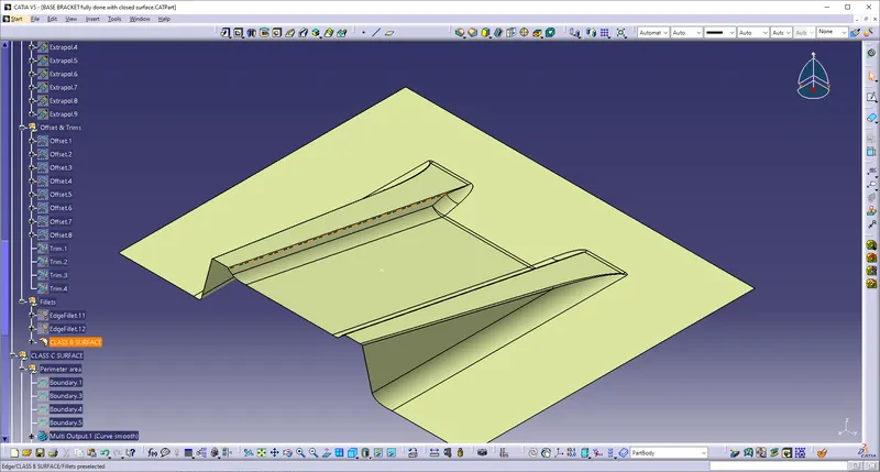
Class C Surface
C-class surfaces are the backside surfaces that can have tool marks, flash, and other imperfections without hurting appearance, function, etc...it also means A and B combined to give C surface.
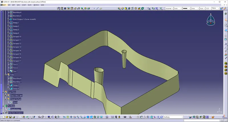
FINAL TRIM:
To create a new gementric set name it as class A & C Join and finish the process finally closed surface the whole body in part body
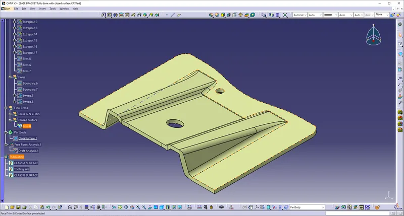
FINAL PRODUCT:
Final product of part body to hide of previous operation.
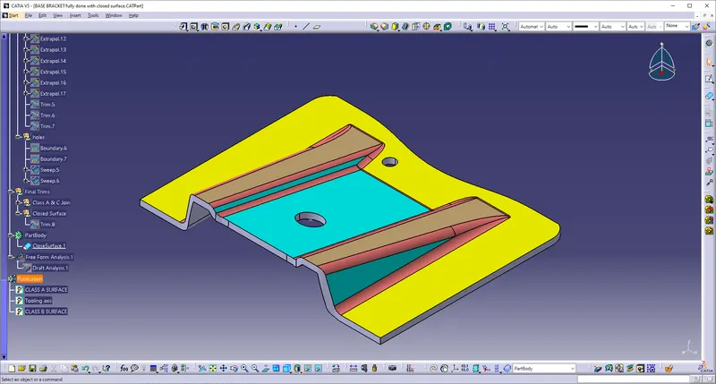
FAMILY TREE:
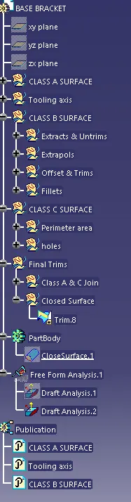
Conclusion
Thus the manufacturable Base bracket was successfully designed and analyzed draft angle using CATIA V5 Surface workbench.