Week 8 - Challenge 4 - Bumper
AIM:
TO Create the Bumper Plastic component through the given Class-A surface. To begin with, the tooling axis for the given Class-A Surface should be created meeting the requirements of the draft angle and at the end perform the Draft analysis on the model. Take the Thickness of the component to be 3mm
OPERATION TO DO :
- Create tooling axis
- create draft analysis for class A surface
- create class b surface
- create class C surface
- create draft analysis for overall surface
- create closed surface
OBJECTIVE:
- To create a tooling direction.
- To perform draft analysis for given A-Surface and prepare the final close body.
- To design the Bumper plastic component by creating the B-Surface and C-Surface using the given Class-A surface.
- Take the Thickness of the component to be 3 mm.
MATERIAL USED IN BUMPER:
- Acrylonitrile butadiene styrene (ABS)
WHY THIS MATERIAL IS USED:
- ABS has a low melting point which enable its easy use in the injection moulding process and 3D printing .It also has high tensile strength and is very resistance to physical impacts and chemical corrosion,which allow the finished plastic to withstand heavy use and adverse environmental condition.
- High dimensional stability (mechanically strong and stable over time).
- High surface brightness and excellent surface aspect.
WHAT IT IS USED?
- It is used in the rear side of the car at the bottom surface.This is used to protect the body of the car for unexpected damage.
FOLLOWED CONSTARINS:
- The change in dimension of the class A surface is not allowed
- Change in thickness is not allowed
- The thickness given to the bumper is 3mm
CLASS A SURFACE:
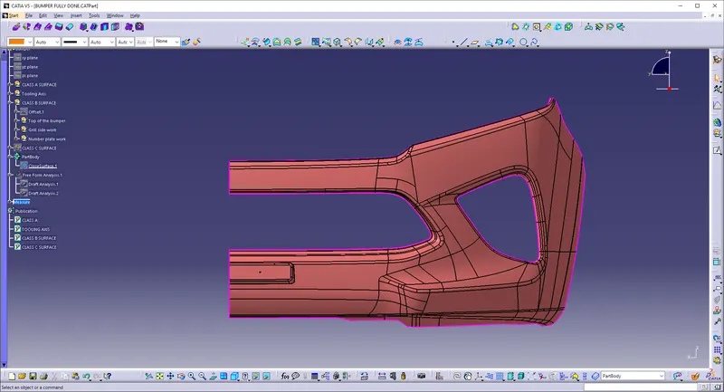
Check the connectivity of the Class A Surface Ensure that there is no gap between the component, using join command. We can visually check it or by clicking boundary command. It has a boundaries outer. Therefore first check completed.
TOOLING AXIS:
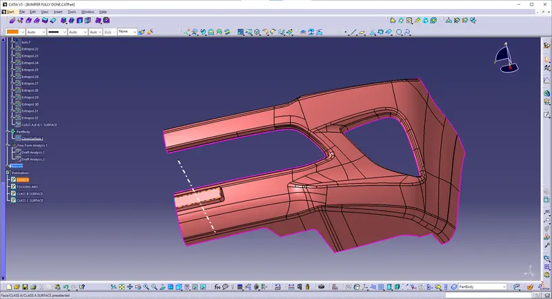
It is very important to give draft angle to the plastic product to avoid damage or defective product output from the mould. The draft angle using in industries are 3 degree.
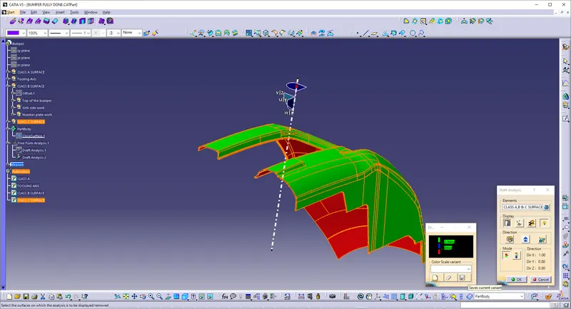
Drag the compus to the tooling axisand kept in center and then click on the compus icon on draft analysis dialogue box, the compus will get active. Once the compus will active again need to aligned along with tooling axis.
Once the compus aligned with tooling axis, click on the model to do the draft analysis, the model is convert into green color then its indicate model is perfect for modeling and if it is showing red in color then click on the draft analysis dialogue box in reverse icon and the model will get turn into green color, after click on reverse icon still the model is in red color the , don't proceed further , and revert back to class A surface engineer.
DRAFT ANALYSIS FOR CLASS A SURFACE:
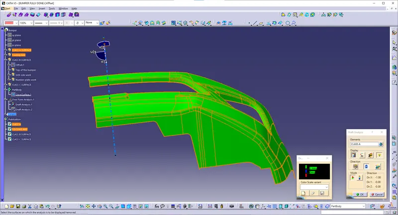
To create a draft analysis for class A surface with respect of y axis because of more visible in y axis
FINAL DRAFT ANALYSIS :
Draft analysis for final body
CLASS B SURFACE:
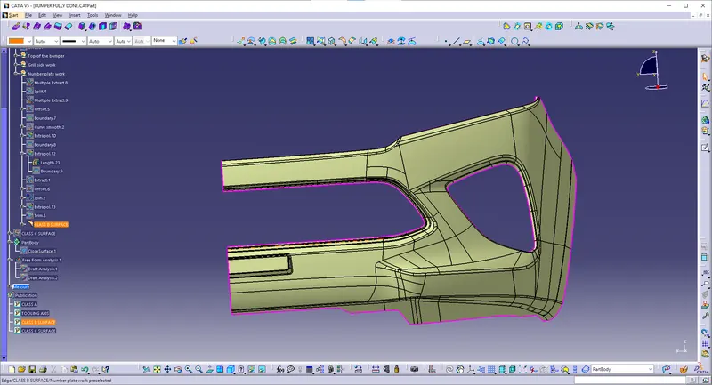
Is created with help of A-Surface by using the Off-set,Trim command,Multi Section,Sweep and Fill command.
We have divided the entire model into base, side walls, inside side walls and outer flange and worked on them one by one
Everywhere we follow same procedure i.e. extract, un-trim, extrapolate, trim and offset.
First base, then side walls. To avoid confusion, we trimmed both together and made them one. Also the fillet was given.
CLASS C SURFACE:
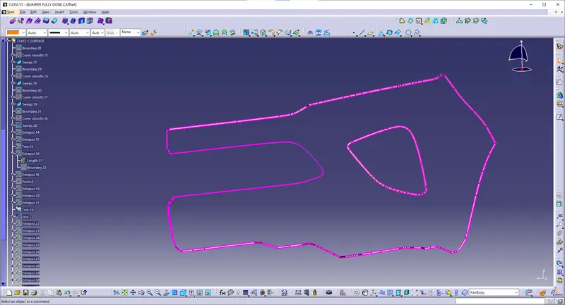
Is created with help of A-Surface by using the Sweep and Boundary command.
In this model, unlike the earlier models, we have used parallel tooling axis. Hence we cannot use ‘with draft direction’ option under sweep.
The C surfaces will mostly be created like shown below
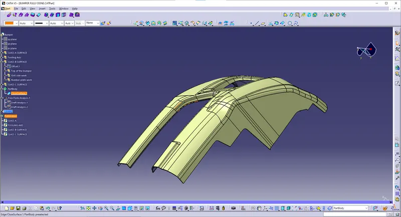
FINAL SOLID BODY: This ia the final stage of the plastic product model,where the final close surface will converted into a solid body.Once the final close surface is created we have to shift to part workbench from surface workbench. In part workbench by using close surface commond the close surface will converted in to solid body.
Once the solid body will created again do the draft analysis for the solid body.
Procedure for creating Closed Body
- Join the Class A and Class C surfaces.
- Trim those joined surfaces with Class B surfaces.
- Go to Part Design and insert a Body.
- Create a closed surface.
PART BODY OF CLOSED SURFACE:
- Go to the part design and close the feature
JOIN A & C SURFACE :
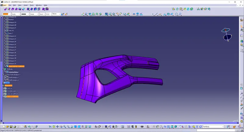
TOTAL SURFACE VIEW OF COIN HOLDER
- TOP VIEW
- SIDE VIEW
- FRONT VIEW
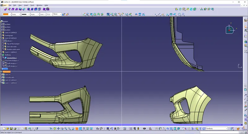
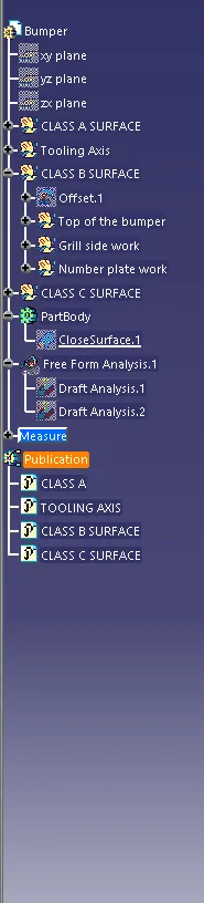
FAMILY TREE OF COIN HOLDER: