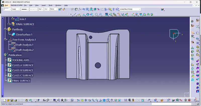
Base Bracket Design
BASE BRACKET DESIGN
- Draft analysis- The Draft analysis is performed based on colour ranges identifying zones on the analyzed element where the deviation from the draft direction at any point, corresponds to specified values. Here I am taking the draft angle 0 to 2.6 degree.
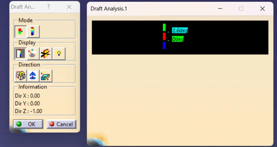
For perform the draft analysis we need to create a Tooling axis and the part should be in the material mode. Then after we will open the draft analysis tool from analysis toolbar. After that we will click on the compass and will keep on the tooling axis and lock it by click on the lock command. And we click on the part then we can see the analysis by blowing the colour in part. I have some result here which is given below.
Class a surface draft analysis-
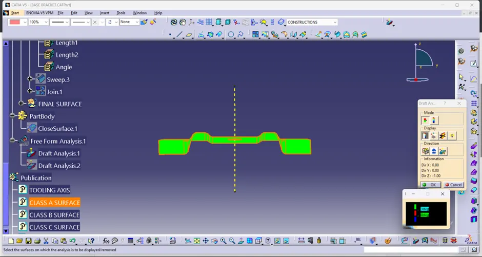
PLASTIC COMPONENT DRAFT ANALYSIS-
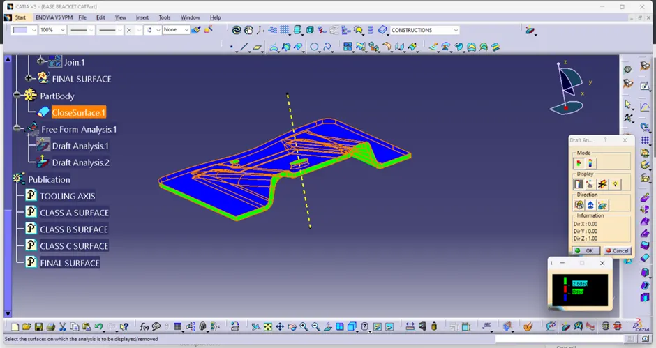
Tooling axis-
- The tooling axis of the product tells us the direction of movement where the part is being produced effectively.
- There are Some advantages if we follow the effective tooling axis like
- The side cores and other things can be reduced.
- The tooling axis is not restricted to a particular direction. It can be produced in that direction where the product can be produced easily.
- Creating the tooling axis by using the Bisecting method-
If we are going to create a tooling axis by using the Bisecting method we need to intersect the class A surface using the intersection command. But before that we should be ensure that which coordinate would be perfect for use the intersection command. So here is the steps to create the tooling axis using bisecting method.
- First of all I have a taken a point with reference of circle and taken a plane on this point with reference of yz plane.
- Then after I have taken a intersection and intersected the class a surface with a reference of plane
- After that I have created two lines on the intersection lines and taken a bisecting line with reference of two lines.
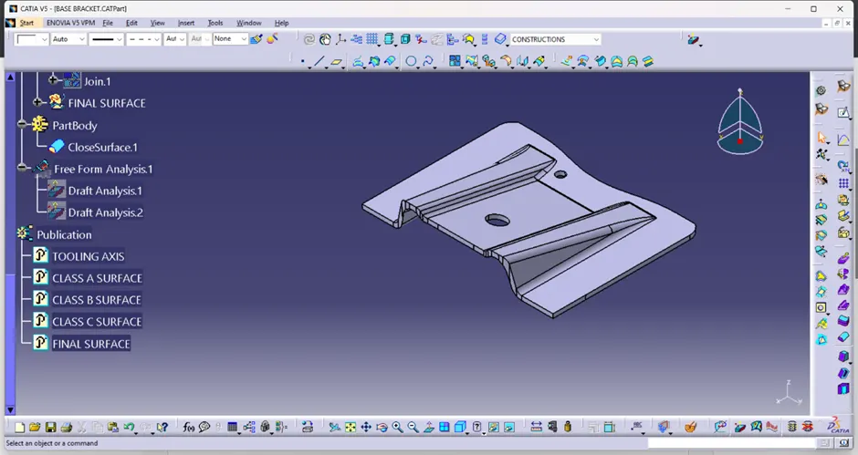
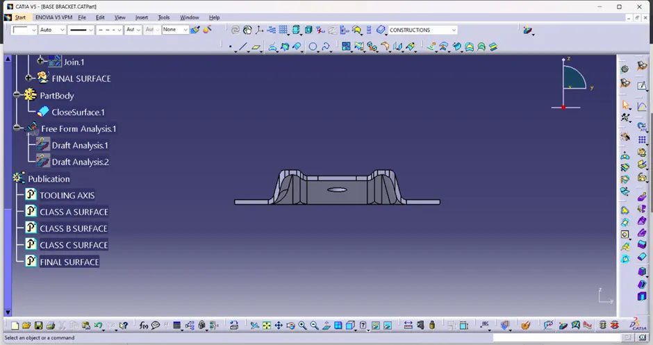
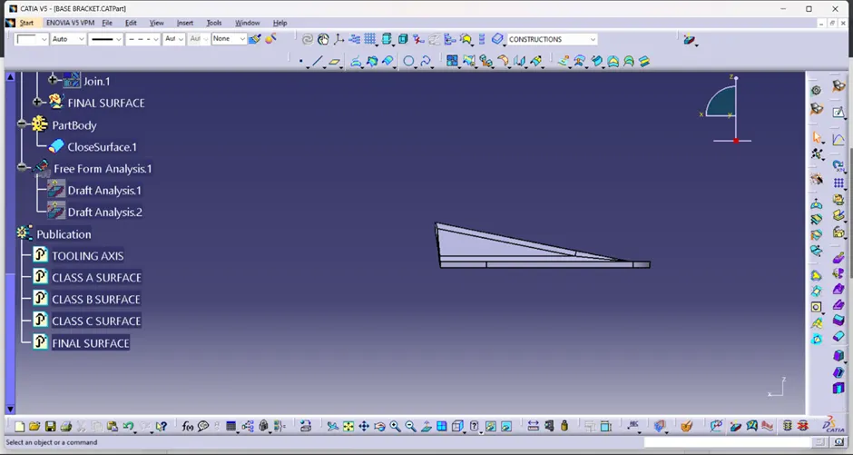
Screenshots of part in different view-
Isometric view-
Front view-
Side view-
Top view-