Week 8 - Challenge 1 - Base Bracket Design
Week 8 - Challenge 1 - Base Bracket Design
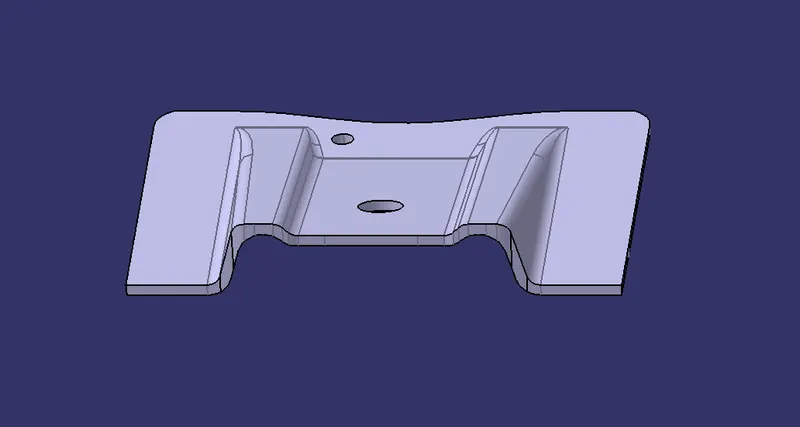
AIM :- The main objective of this challenge is to create the Base Bracket Plastic component through the above-given Class-A surface, by giving the 'Tooling axis' and 'Draft analysis' to the class-A surface of the base bracket.
Index of tooling axis
- Check the connectivity of the surface and ensure there will be no gap between the surfaces and then define the tooling axis.
- Connectivity of the surface can be done by two ways by join method and by boundary method.
- In the case of Class A the surface below is called core and the surface above is called cavity.
- Split the surfaces in to three profiles then Identify the surface which is not possible for tooling axis and check which direction is best fit for tooling axis and define the draft direction.
- First create a dummy tooling axis which is in concentricity with the hole.
- Create the tooling axis using the intersect method by creating a bisecting line.
Steps for tooling axis creation :-
- A tooling axis should be created such that, the surfaces of the part must clear the tooling axis and the elements of the component can be created in that direction.
- we define a dummy tooling direction based on the flat surfaces and the holes the surface contains. And the areas which may create some issues when this dummy tooling direction is taken as the main tooling direction and the sketches of these areas should be obtained and concerning those sketches, the main tooling direction has to be obtained.
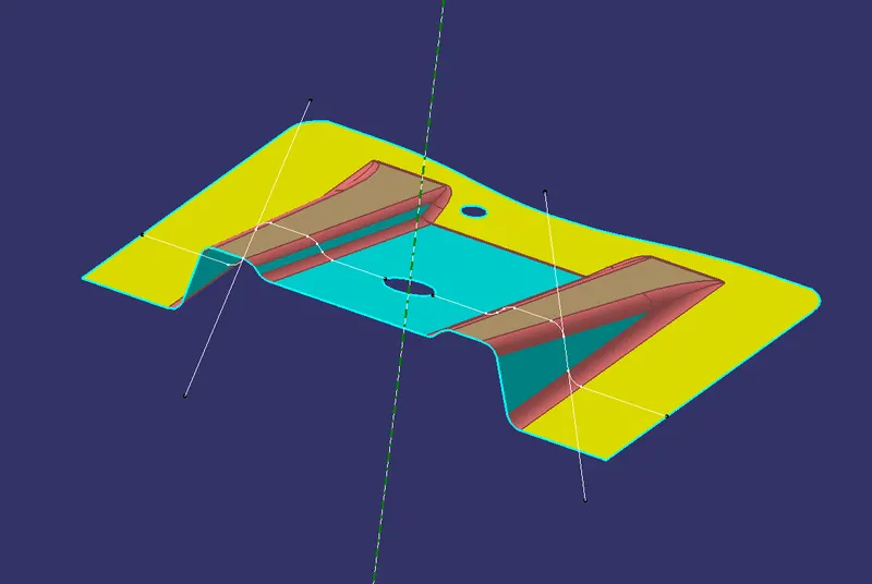
- For creating the tooling axis, we first intersect the component with the YZ plane only since a few elements of the component cannot be manufactured in the XZ plane.
- From the intersected surface we draw two lines from the boundary of the surfaces that we find close to not fulfilling the tooling axis.
- We then bisect these lines and get the tooling axis for the bracket.
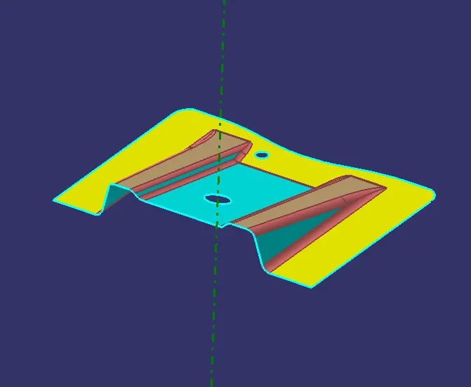
Draft analysis
The draft analysis technique is used to analyze whether our part model created in CAD is manufacturable based on the draft condition applied. Here the part should get easily removed from the panel dies (in case of Sheet metal part) or Mold (in case of plastic)
- Draft allows for the component to release from the mould, most parts or applications require a minimum of 0.5 to 1 degree draft angle and 3 dgree draft angle is widely used as per the norm.
- Change the material mode to customize mode before moving to the draft analysis.
- Insert –analysis-feature draft analysis
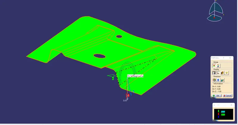
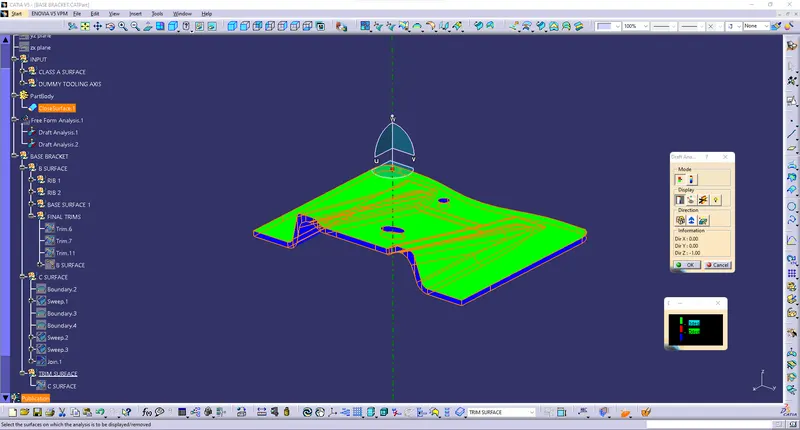
- Defining the draft direction Select draft analysis from the tool bar and click on the compass symbol and pull the compass from the right side top corner of the workbench and place it on the component where want to do the draft analysis. ‘W’ of the compass and tooling axis should be aligned on the same line.
- By clicking the on the surface and using the flipping tool we can assign the Flipping direction .
- Click on the lock symbol and click on the component then a table will appear it shows the draft value.
- Analysis under running point and move the mouse on the surface and it will show the details of the surface deg direct.
DRAFT ANALYSIS ON CLASS A SURFACE
DRAFT ANALYSIS ON PLASTIC COMPONENT
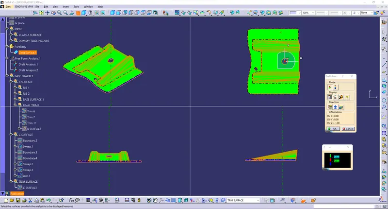
ALL VIEW FOR SOLID COMPONENT WITH DRAFT ANALYSIS
CLASS B SURFACE:
To create the class B surface, I considered the entire surface has 3 parts 'Rib-1, Rib-2, and Base surface'. If we directly offset the class A surface, fillets may lead to cause an error, to avoid the errors we need to extract the surfaces and untrim the extracted surfaces and extrapolate those untrimmed surfaces with point continuity. Now trim those extrapolated surfaces to the required shape. And finally, fillets were given to the final trim.
1.RIBS
- To create a rib by extract the rib faces from the class-A surface.
- After extraction to untrim them for collide faces and extend up to some point
- To use Extrapolate for to extend the untrim surfaces
- To use trim tool for remove unwanted surfaces
- To offset the ribs down to 2.5 mm
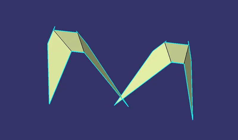
2.BASE
- First we extract base from class A surface .

- To create a base surface and extrapolate to meet the ribs for remove unwanted surface.
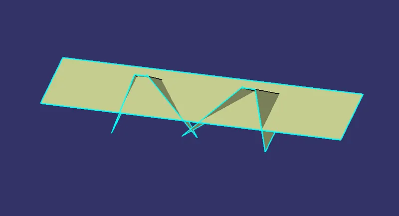
- Base surface with ribs after the trim the unwanted surfaces.
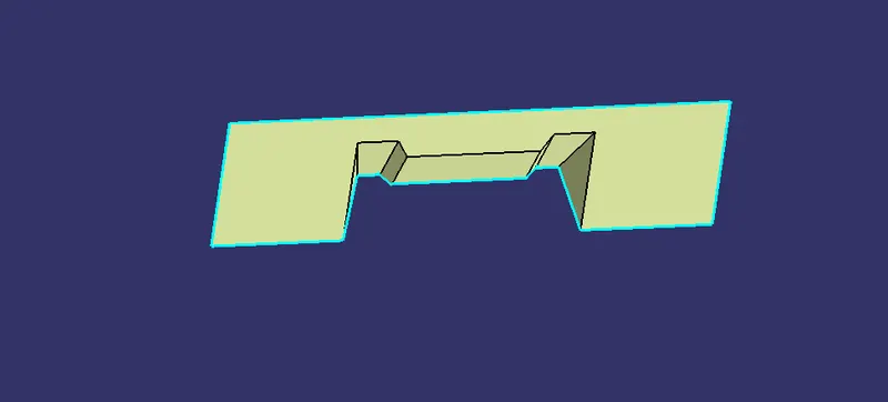
- Apply fillets on all corners with redius of 3mm+thickness.
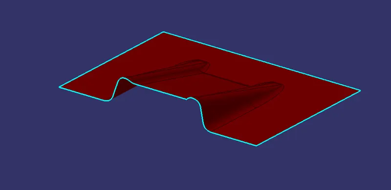
CLASS C SURFACE:
The Class C finish allows more imperfections than Class A or B. Class C is often specified for interior surfaces not readily visible, surfaces that will be covered by another part when assembled, or surfaces which the Customer feels do not need to meet a high cosmetic finish.
- C surface has been created from with reference to the boundary lines of class A surface.
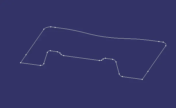
- Sweep it with reference to the tooling axis then the holes are created by following the same method.
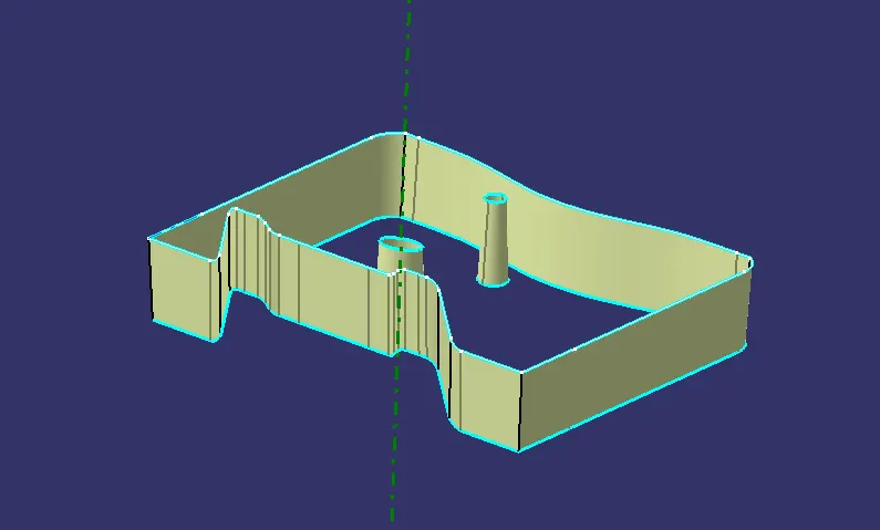
- Then join C surfaces and holes with class A surface.
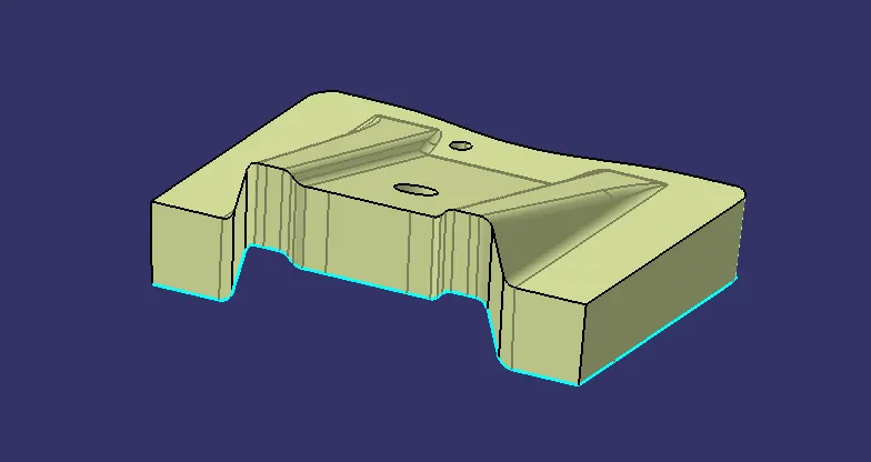
- Finally trimmed the join with B surface to get the final compenent.
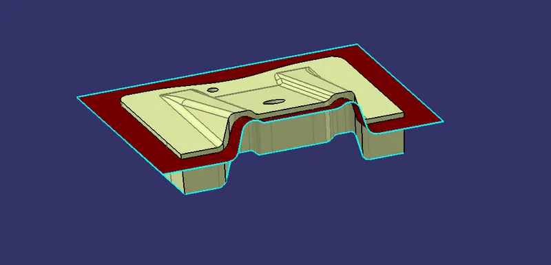
- By using the final Trim Create the solid body by using close surface on part workbench.
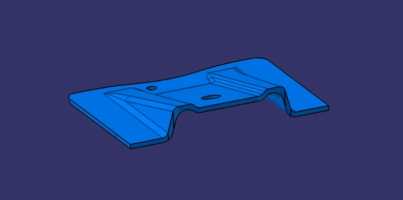
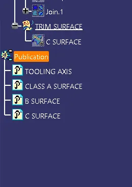
FEATURE TREE
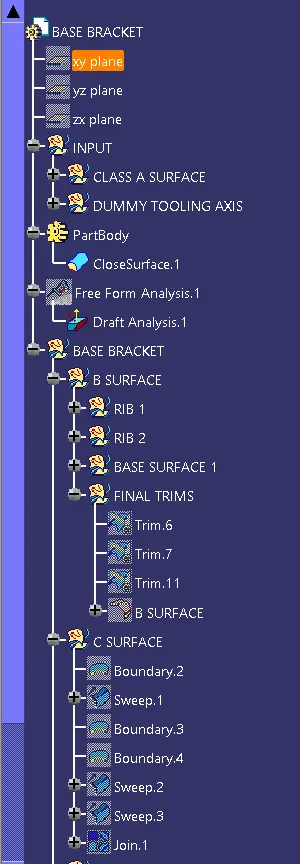
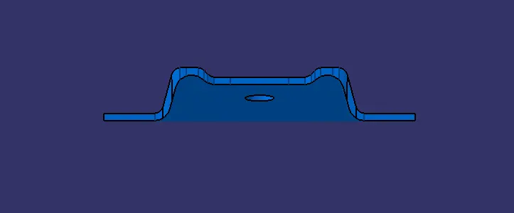
FRONT VIEW
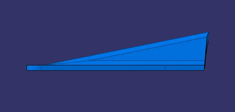
SIDE VIEW
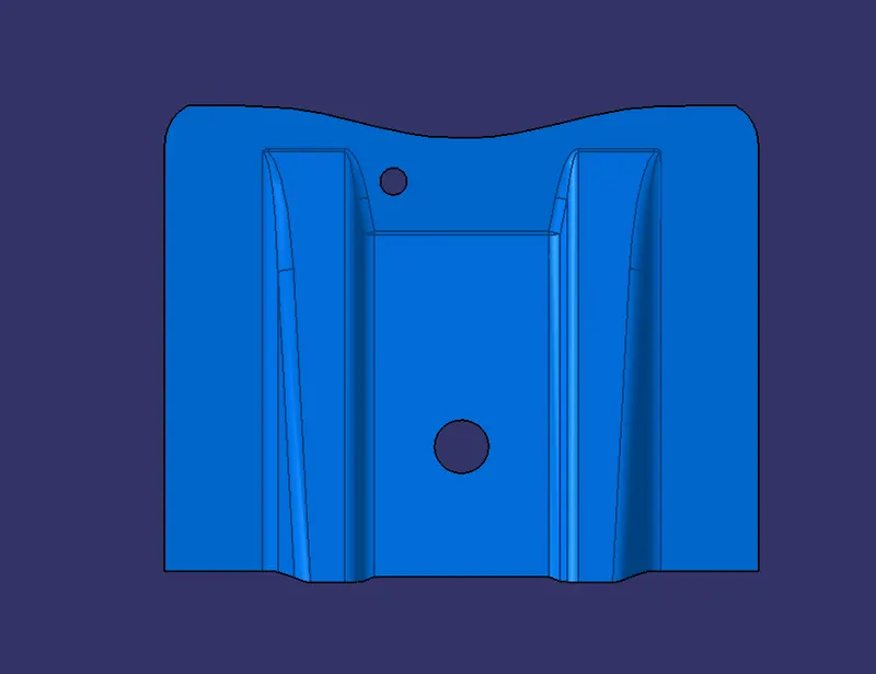
TOP VIEW
ISOMETRIC VIEW
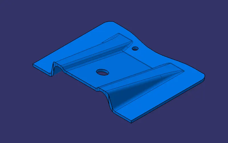
CLOSE SURFACE BODY
To create a solid body from the closed surface, I used the 'closed surface' command in part workbench. Click on the closed surface command in part workbench and select the final trim of the closed body and click ok. The required solid body is created by using the closed surface.