Week 8 - Challenge 1 - Base Bracket Design
Question:-
Create the Base Bracket Plastic component through the given Class-A surface. To begin with, the tooling axis for the given Class-A Surface should be created meeting the requirements of the draft angle and at the end perform the Draft analysis on the model
Answer:-
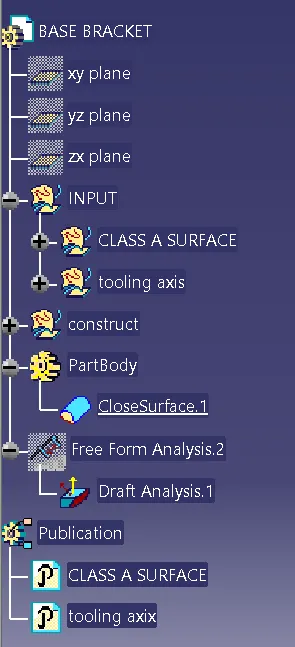
- Tree Structure
- Ensure Proper Tree Structure
- Geometrical sets should have a proper name based on the sketches present inside of it
- All the sketches should be created under the Geometrical set
- Use the Close Surface feature to make a solid body from the surface.
- Publications: Use the publication option and publish the below
- Tooling Axis
- Class A, B, and C surface
1.Tree Structure:-
2.Tooling Axis:-
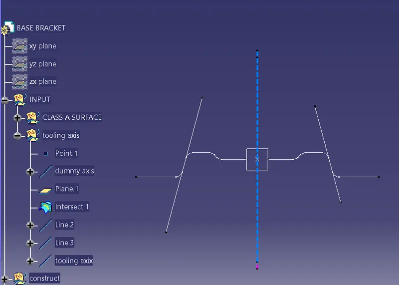
Steps:-
- Create a point and plane for respective 3D,
- create a intersection line for YZ plate,
- create a line for which we have to create a draft angle as tooling axis
- create a bisecting line for the both lines respective to points
- hence the final line is tooling axis
3.Draft Analysis:-
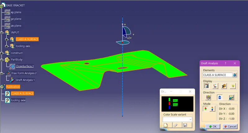
Steps:-
- find a draft angle with respect to the tooling axis
- The given angle is min of 3 degree
- hence the green shows the maintaing of angle is correct
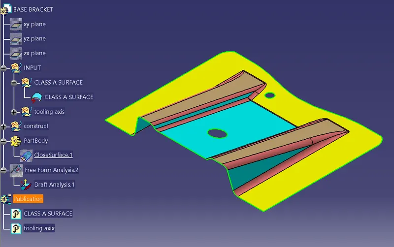
Base Bracket:-
Surface A:-
Surface B:-
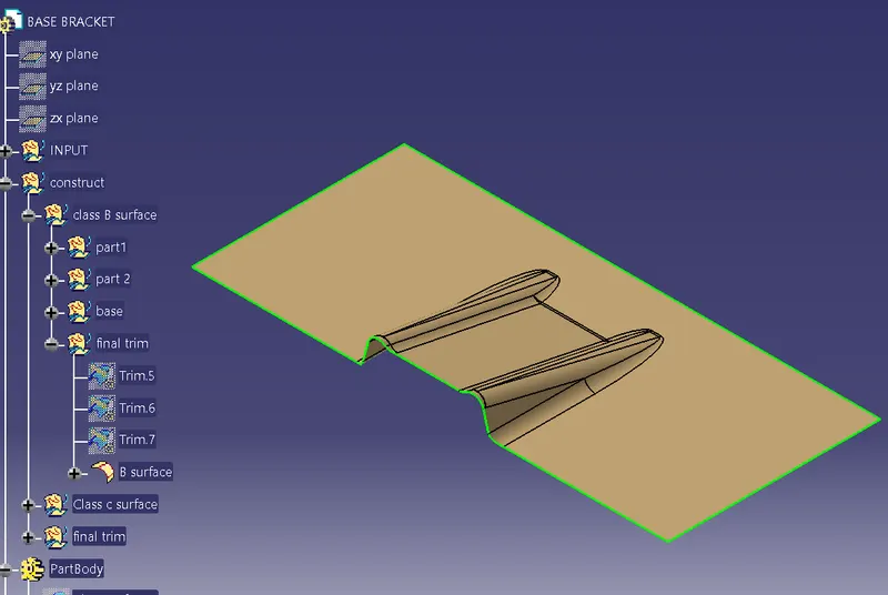
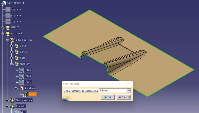
Fillets:-
Note:- fillet is maintain at 5.5 that means 2.5 off set distance and old radius is 3
fillet radius 3 + 2.5 = 5.5
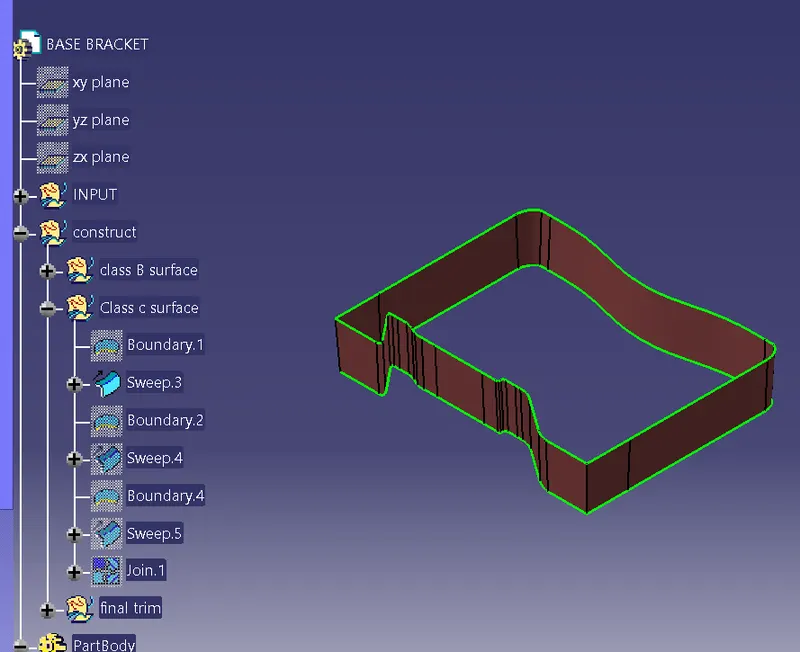
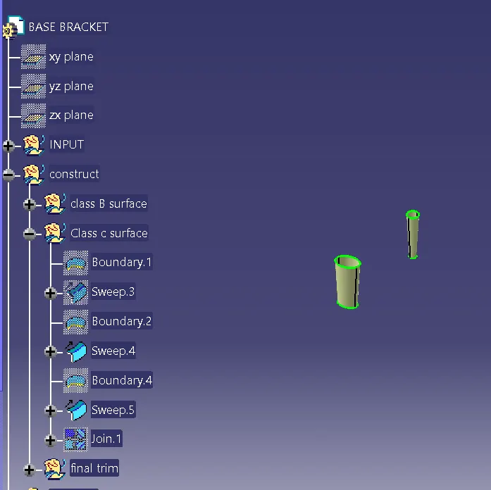
Surface C :-
Final Surface :-
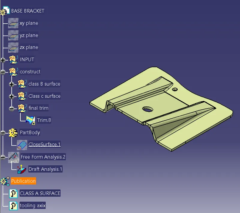
Final product Draft analysis:-
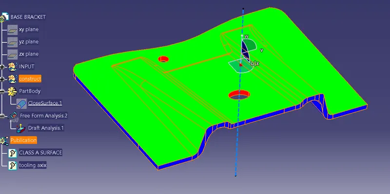
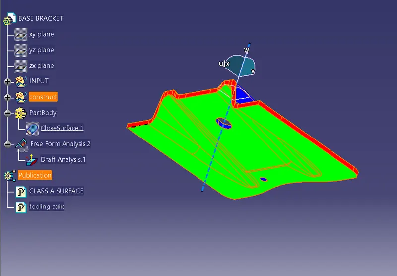
Both Side the shows the postive for both side becase of maintain the 3 degree angle
hence it shows green
Closed Surface Feature:-
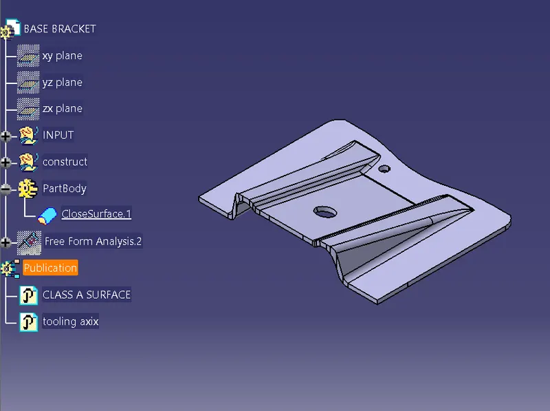
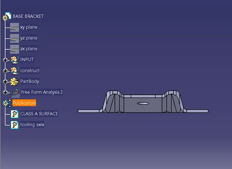
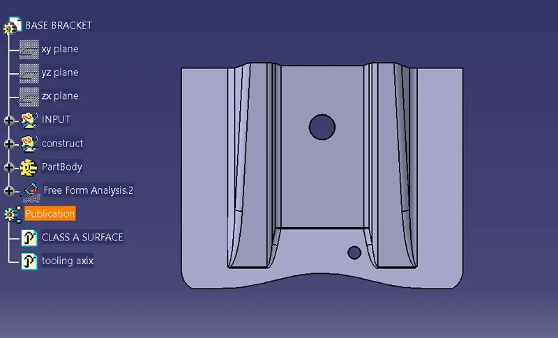
Result:-
- Screenshots of the Draft analysis report for both the given Class-A surface and the final plastic component
- Image of the complete Draft analysis
- Images of the color scale variant
- Screenshots of the solid model with the proper color code of the draft angle in various orientations (Isometric, Front, Side, and Top View)