Week 9 - Attachment Feature Creation (Ribs & Screw Boss) - Challenge 1
Aim :-
To Create the Attachment Features (Ribs & Screw Boss) on A Door Handle through the given Class-A surface by creating tooling direction, the tooling axis for the given Class-A Surface should meet the requirements of the draft angle i.e. minimum 3°and at the end to perform the Draft analysis on the model.
Class A Surface :-
The Class-A modeling process typically starts with a fully developed design, either as a scanned clay model or an Alias model. Because the design isn't changing, the modeler has the time to build surfaces to the highest quality standards, ready for production.
The challenge for Class-A is to combine the need for:
- Aesthetic Quality – Continuity and Highlights
- Engineering Requirements – Flanges and Fit
- Production Requirements – Modeling Tolerances
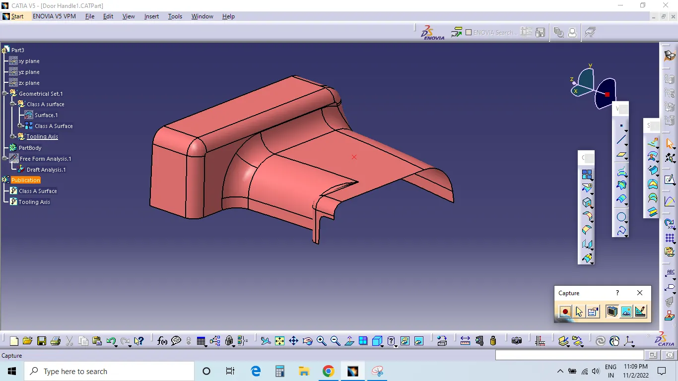
Tooling Axis :-
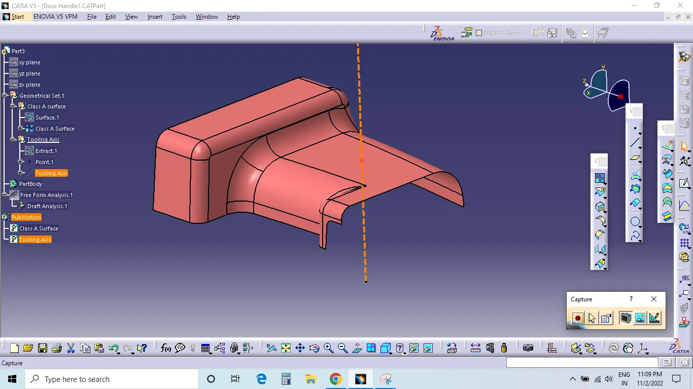
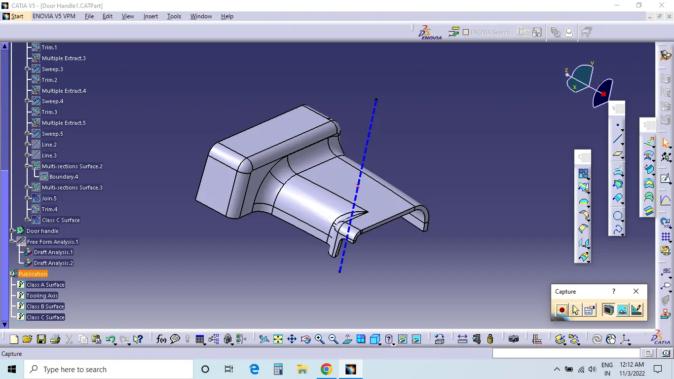
- Tooling axis here created is by selecting one of the natural axes as it clears the draft.
- Here, tooling axis is created by extracting one of the surfaces for creating a point and a new axis is created at that point.
- So, a flat face is extracted and created a point at its centre. Axis is also created at that point.
- Now, line is created using line tool and giving line type as point-direction and selected the point and direction for creating tooling axis and tooling axis is created along x direction.
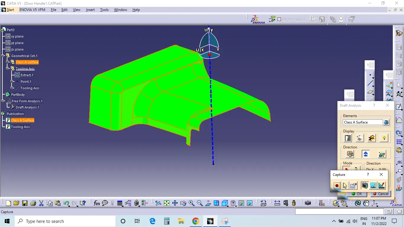
Draft Analysis for Class A Surface:-
- Change the view mode to material shading
- Align the Compass with Tooling axis.
- Lock the draft direction and perform the Draft analysis.
Creation of Class B :-
- To create the class B surface, offset the class A surface inside as per our thickness requirement (here the thickness is 2.5mm, so I offset the class A to 2.5mm inside).
- Once the offset is created, we can observe some patches on the offset surface by taking the boundary for the offset surface, those patches are formed due to the fillets on the class A surface.
- We covered the patches by using the different surface commands (multi sections surface, fill, blend) in the Generative Shape Design workbench.
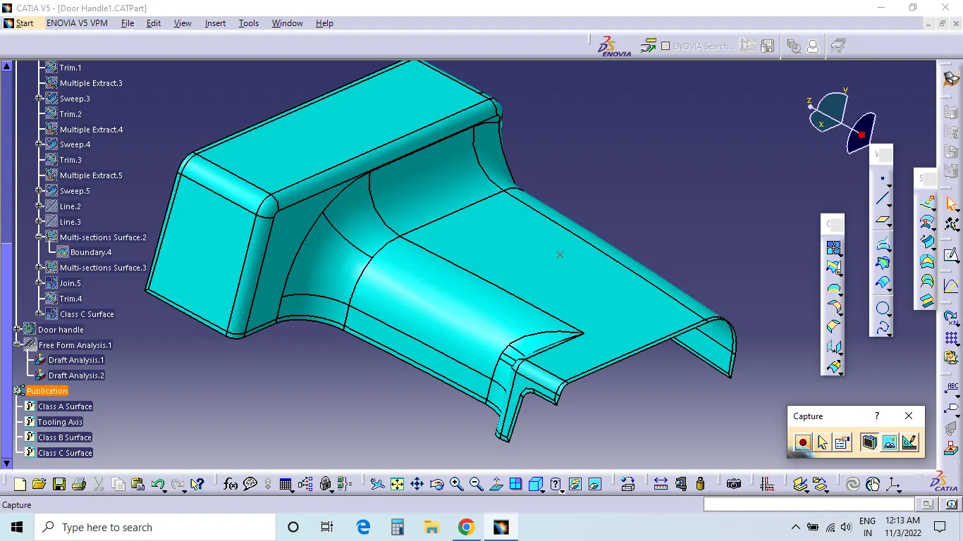
Creation of Class C :-
- To create the class C surface concerning the boundary of the class A surface, I used the sweep command. Initially, I extracted the boundary of the class A surface with tangent continuity, and I sweep the extracted boundary concerning the surface at 93deg (for draft angle) for 5mm to intersect properly with the class B surface.
- Once we sweep all the surface boundaries of class A, extrapolate the swept surfaces until both surfaces got intersected properly, and trim them to remove extended extrapolated surfaces to get a proper sweep boundary throughout the entire surface, including the centre hole of the bumper.
- Now, join both class A and sweep boundary to get the complete class C surface.
- Now Class A surface and Class C surface is joined.
- Now Class B surface is also trimmed with the obtained surface to get the closed surface.
- Boundary check is done to check for any open boundaries in the part. The closed surface then obtained moved to part design and close surface tool is used to obtain the part.
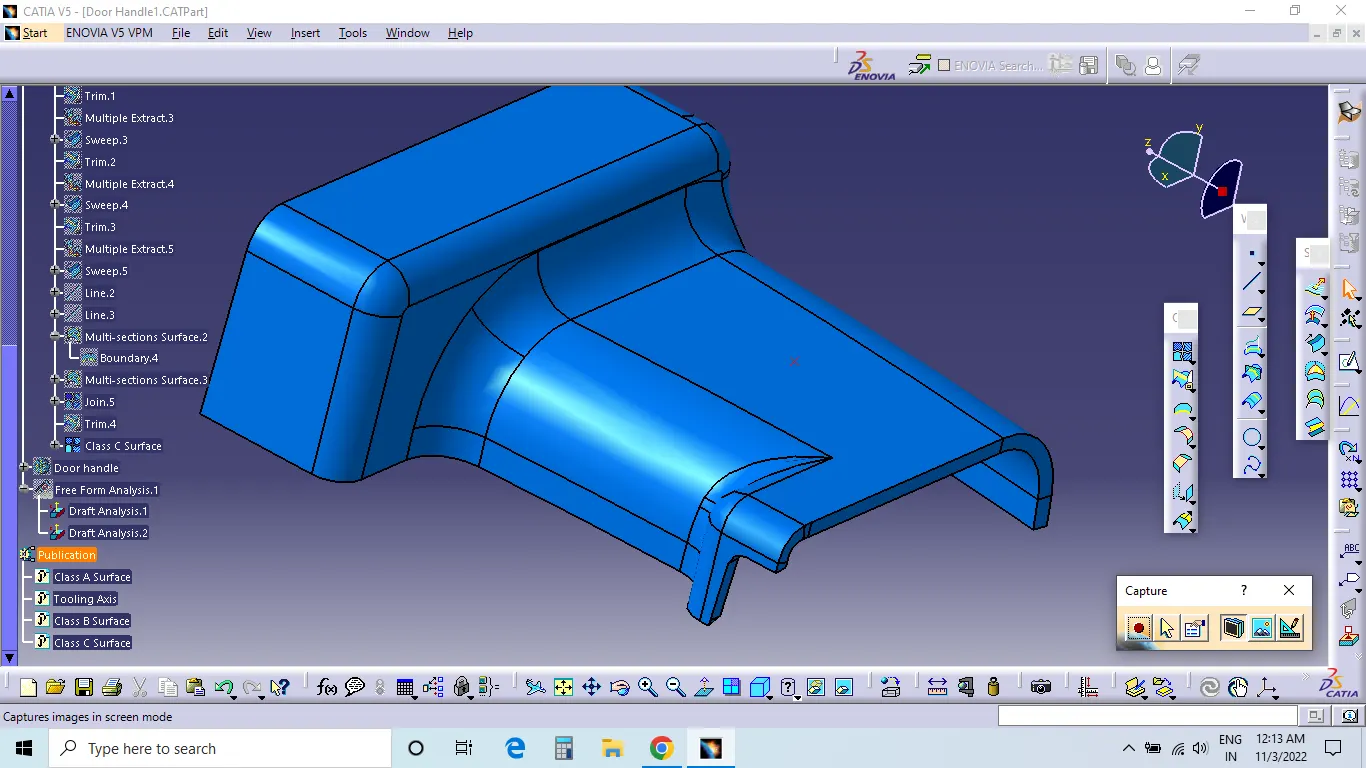
Creating the final surface of Door Handle :-
- First step is to join the CLASS-A surface with CLASS-C surface.
- Then Trim the Joined surface with CLASS-B surface to achieve the final Door surface.
- Go to the part design work bench and using the close surface command create the base bracket solid part body
3D Part model in various orientations (Isometric, Front, Side, and Top View)
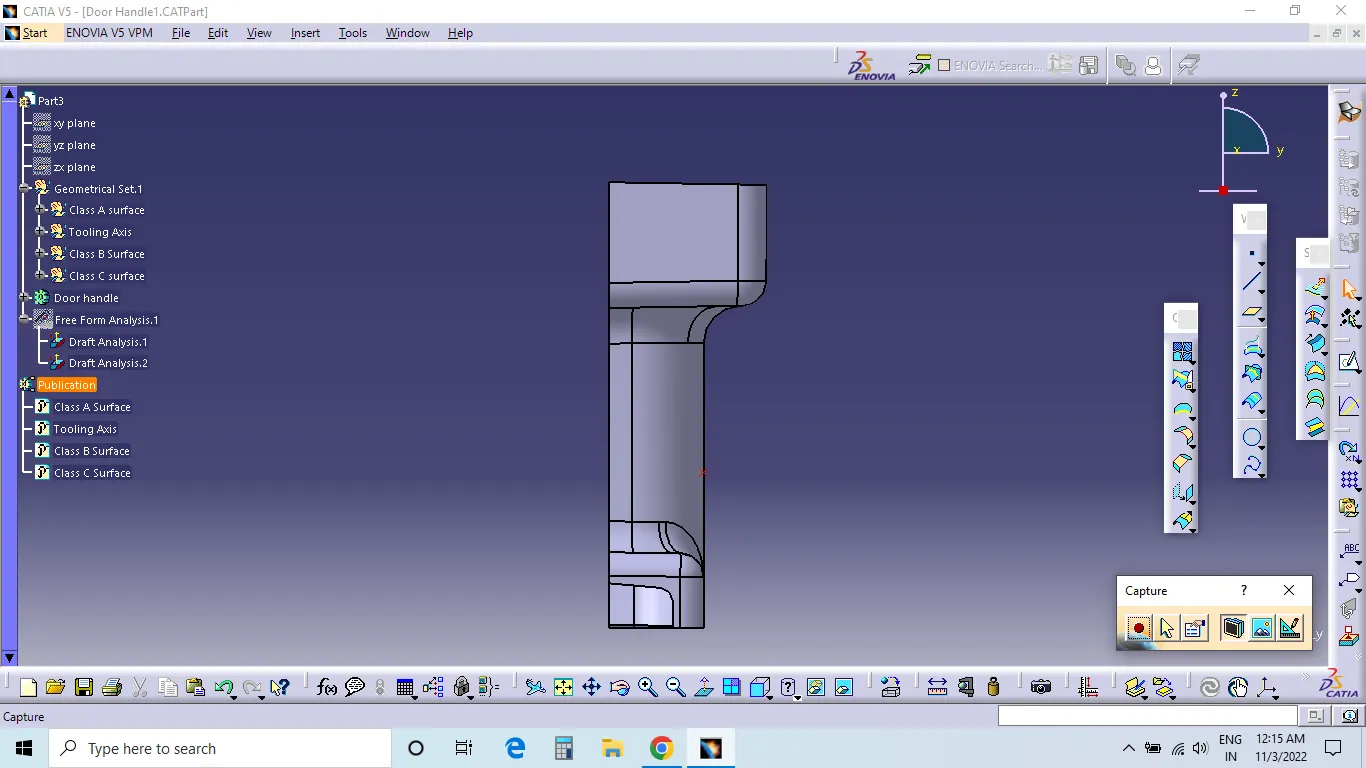
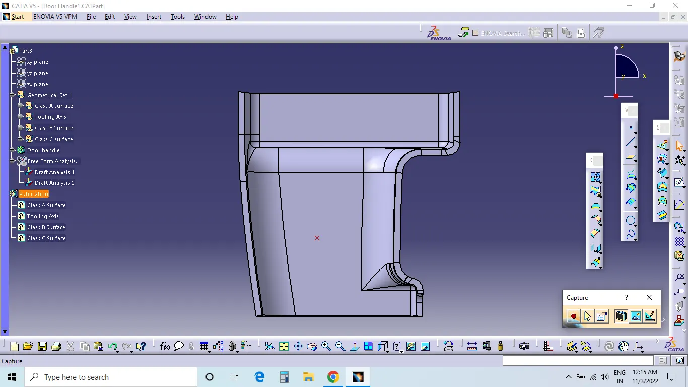
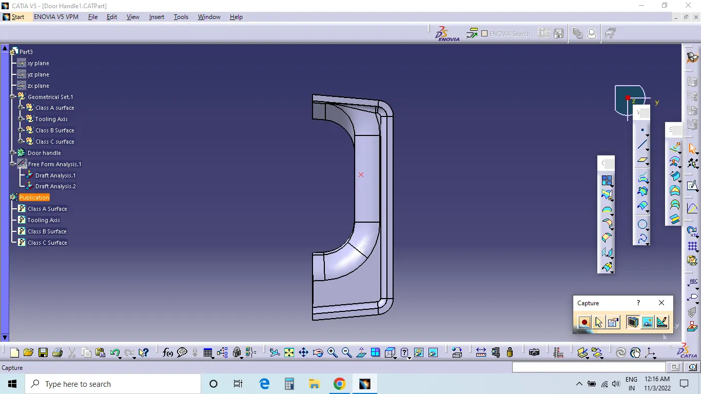
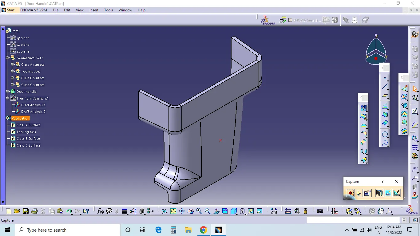
Tree Structures :-
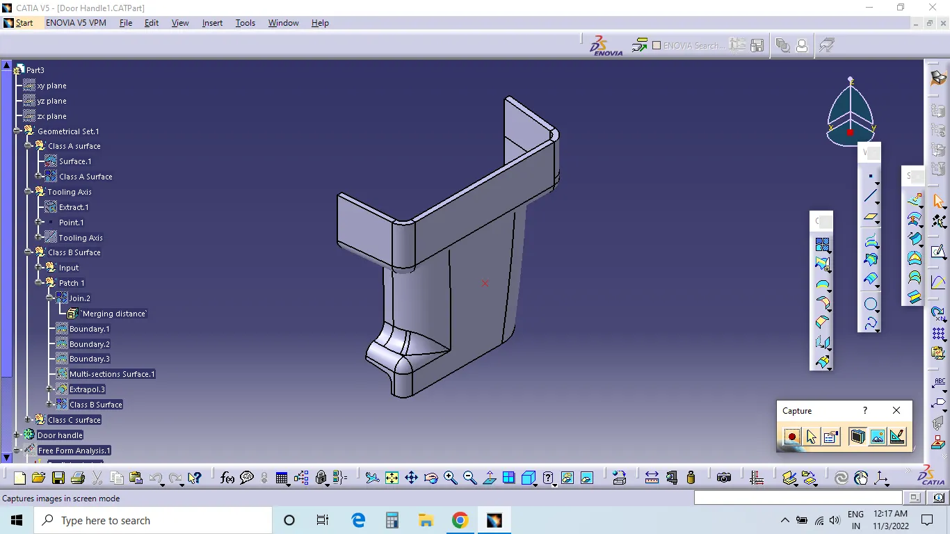
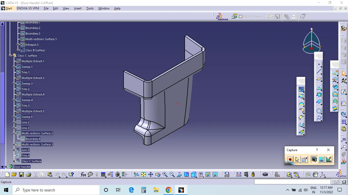
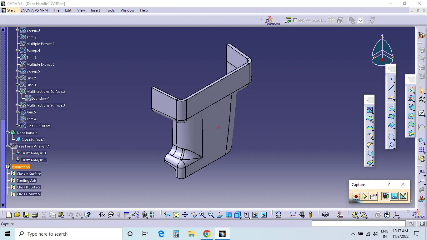
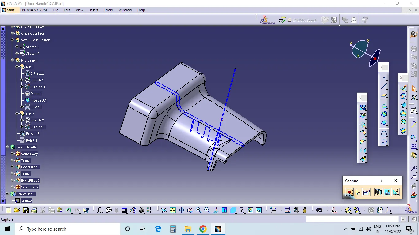
Draft analysis of the Final part body
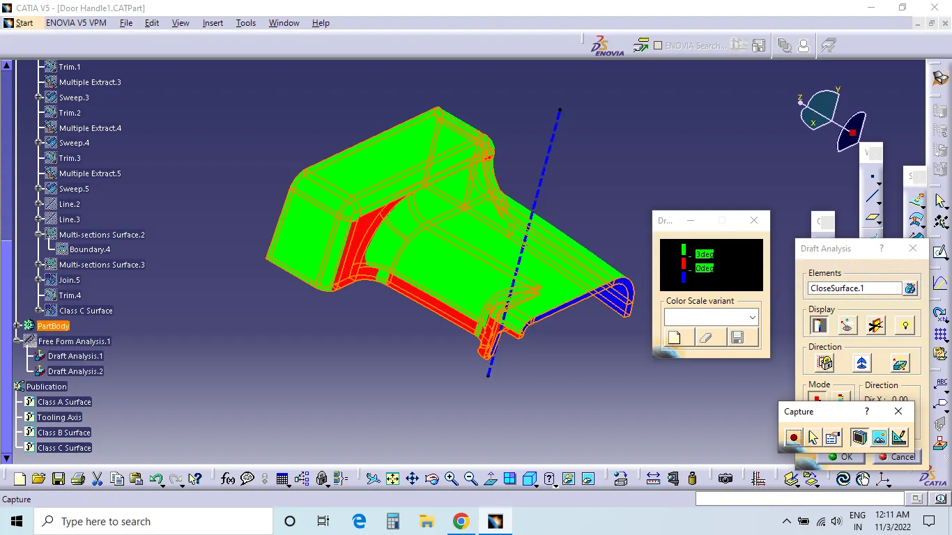
Same procedure for the draft analysis of CLASS-A surface is followed.
- Change the view mode to material shading
- Align the Compass with Tooling axis.
- Lock the draft direction and perform the Draft analysis.
--> Introduction to Ribs & Bosses :-
Ribs :-
- Rib provides an economical way to increase stiffness and strength to the mould parts without increasing the overall thickness of the wall.
- It is thin protrusion that extended perpendicular from the wall.
- Ribs should neither be too long nor too thick, otherwise, it will increase the difficulty of injection moulding, causing problems such as voids and sink marks on the back.
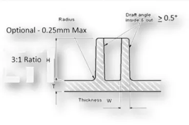
Design Guidelines For Ribs :
- Draft
- Thickness
- Height
- Spacing
- Thickness at the Top
- Optional Radius
- Design suggestions
1. Thickness of the Rib = 0.4t = 0.4*2.5mm = 1mm
- Measure base thickness of the Rib at the tangent of radius if raii are modelled.
- The larger the area of at the base of Rib, the more retained heat.
- The retained Heat causes more shrinkage, which causes sink
2. Height of the Rib = 5t = 5*2.5mm = 12.5mm
3. Draft --> 0.5 degree minimum per side.
- Allows the Rib to release from the mould.
4. Spacing
- Ribs should be spaced so that the steel between the Ribs is at a
Height / Width Ratio , 3:1 for steel & 2:1 is preffered
- Prevent thin steel conditions which leads to cracking
5. Minimum thickness at the tip = 0.75mm.
6. Radius = maximum 0.25mm.
7.
| Wallstock(mm) |
Max Rib Thickness at Base @40% (mm) |
Min Rib Thickness @ tip(mm) |
Minimum Draft (Degree) | Maximum Rib Height(mm) |
| 2.5mm | 1mm | 0.75mm | 0.5 | 14mm |
| 3mm | 1.2mm ` | 0.75mm | 0.5 | 25mm |
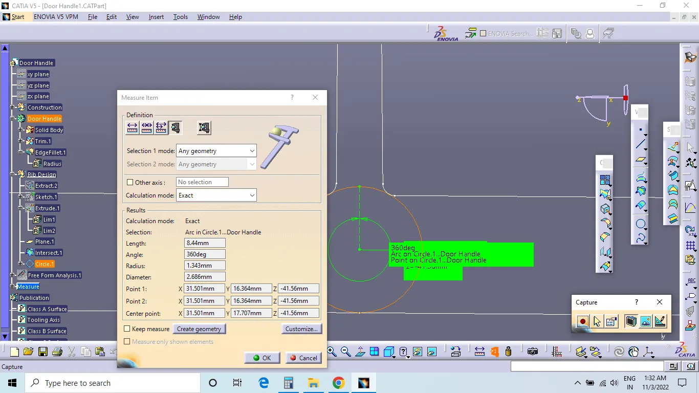
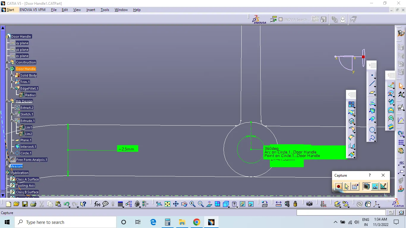
Rib Root thickness analysis :-
- Insert the plane Perpendicular to the Ribs
- Click on the intersection, Select the complete body with reference to the plane and click Ok.
- Then have to sketch a circle which tangent to the Rib base or root area by using tritangent type circle. The value must be within 30% greater of the wall thickness.
Bosses :-
- Bosses are common structures on plastic parts in home appliances and interior and exterior of auto-mobiles, mainly for positioning and fastening.
- Screw boss are used as a point for attachment and assembly, most common in as cylindrical projection with hole design to receive screw or other types of fastening hardware.
- The base of bosses often cause sink marks on the back surface of a part, this is because of the large wall thickness. The solution is to core out some material at the base.
Design Rules for Screw Bosses :-
- Draft = 0.5 degrees on walls of Bosses
- Thickness = Typically 40% of nominal wall at Base
- Height to Diameter Ratio to be 3:1.
- Optional Radii = Max 0.25mm
- Boss Gussets
- Coring out Bottom
- Planning ahead for type of Ejection.
- If Less than 25mm tall, draft is not required when sleeve ejection is used.
- over 25mm tall, draft is required on outside wall only if Sleeve ejection is used.
- If Sleeve ejection is not used, Draft is required on all Walls.
Final Part with Rib & Screw Design :-
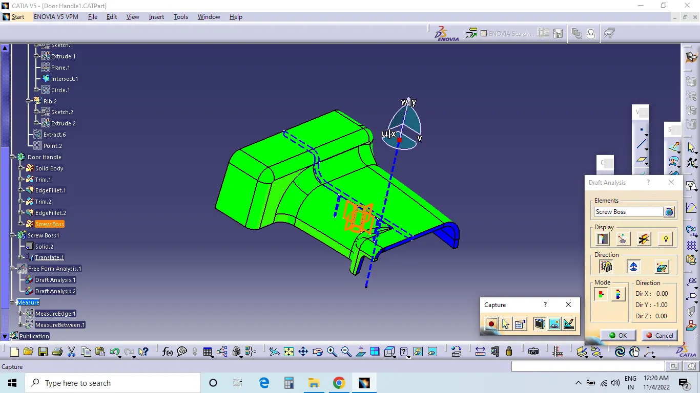
CONCLUSION: Thus I have created the "Ribs and Screw Bosses for Door Handle" model using Class A Surface